


38
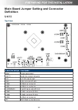
HARDWARE INSTALLATION
HARDWARE INSTALLATION
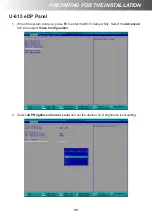
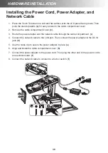
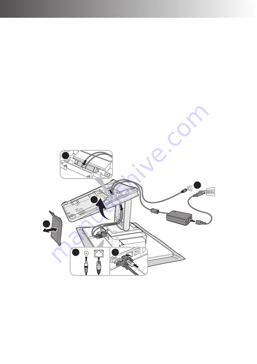
Installing the Power Cord, Power Adapter, and
Network Cable
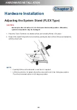
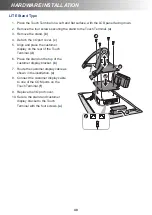
1. Place the Touch Terminal on a soft and flat surface, with the LCD panel facing down. Then
push the stand upwards
(a)
for easy access to the cable compartment cover.
2. Remove the cable compartment cover
(b)
.
3. Route the power adapter and the network cable through the cable compartment.
(c)
4. Connect the network cable to the LAN port. Then connect the power adapter to the DC IN
jack.
(d)
5. Use the cable clip to secure the power adapter in place.
(e)
6. Align and install the cable compartment cover.
(b)
7. Connect the power adapter to the power cord. Then plug the other end of the power cord to
an electrical outlet.
(f)
8. Connect the network cable to connect to a hub or switch.
(f)
a
b
c
f
d
e
Summary of Contents for H-610
Page 1: ...HiFive Series Version 2 0 User Manual ...
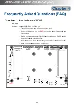
Page 7: ... 7 Chapter 4 Frequently Asked Questions FAQ 44 Question 1 How do I clear CMOS 44 ...
Page 12: ...12 INTRODUCTION Physical Dimensions VESA Mount H 610 ...
Page 13: ...INTRODUCTION 13 H 614 H 615 ...
Page 14: ...14 INTRODUCTION Standard Display NANO Stand Type H 610 NANO Stand Type H 614 ...
Page 15: ...INTRODUCTION 15 LITE Stand Type H 610 LITE Stand Type H 614 ...
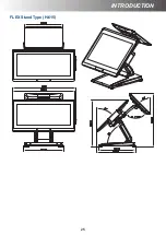
Page 16: ...16 INTRODUCTION FLEX Stand Type H 610 ...
Page 17: ...INTRODUCTION 17 FLEX Stand Type H 614 ...
Page 18: ...18 INTRODUCTION FLEX Stand Type H 615 ...
Page 19: ...INTRODUCTION 19 VFD Customer Display LITE Stand Type H 610 ...
Page 20: ...20 INTRODUCTION LITE Stand Type H 614 FLEX Stand Type H 610 ...
Page 21: ...INTRODUCTION 21 FLEX Stand Type H 614 ...
Page 22: ...22 INTRODUCTION FLEX Stand Type H 615 ...
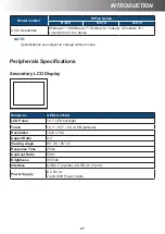
Page 23: ...INTRODUCTION 23 Secondary LCD Display FLEX Stand Type H 610 ...
Page 24: ...24 INTRODUCTION FLEX Stand Type H 614 ...


