background image


XM-DVR Pro

 Dual Channel DVR                                          Page 13 of 32 

December 2009                                                                 Manual Rev 3.05 

Camera Installation 


WARNING

 All components must be positively mounted to withstand high g-load, 

shock, and vibration. In the event of high g-load, improperly mounted components 
may become detached causing serious injury or death. All components must be 
checked for safe and secure mounting before each use. 

 
Cameras can be mounted virtually anywhere on the vehicle. Datatoys bullet 

cameras are waterproof, shielded, and completely potted for vibration resistance. It is 
recommended you mount the cameras in a central mounting position help with image 
stabilization.  


Cable Installation 


WARNING

 All components must be positively mounted to withstand high g-load, 

shock, and vibration. In the event of high g-load, improperly mounted components 
may become detached causing serious injury or death. All components must be 
checked for safe and secure mounting before each use. 
 

CAUTION 

All connections must be hand tightened. Over tightening of connections 

may damage the internal water seal of the connector.  
 

CAUTION 

Sharp edges of zip ties or cable wraps may sever or create a short in the 

cabling. Zip ties and cable wraps must not be over tightened. 


All Datatoys cabling features a 4-PIN, waterproof, positive locking, male or 

female connection. Patch cables may be used to extend any Datatoys 4-PIN 
connections. Please refer to the table below to ensure cabling is routed in the proper 
orientation. 


Device 

Gender to mate with 
DVI harness 

Gender to mate 
with device 

Camera 

Male 

Female 

Microphone 

Female 

Male 

AV-Out 

Female 

Male 

Switch 

Female 

Male 


Cabling should be attached to a solid structure with zip ties, or cable wrap. At no 

point should Datatoys cabling route in parallel with cabling or devices emitting EMI/RF 
interference. When cabling must cross an EMI/RF emitting line their intersection 
should perpendicular to one another. 

 
Once cabling and all other components are installed, connect the system per the 

connection instructions on page 8. 


XM-DVR Pro

 Dual Channel DVR                                          Page 14 of 32 

December 2009                                                                 Manual Rev 3.05 

Using the System 


Before You Begin 
 

Before you begin using the XM-DVR Pro please complete the following check 

list. 


Using a RiData 300X card purchased from an authorized dealer. 


Recorder is installed per the installation instructions. 


Power supply is installed per the installation instructions. 


Cameras are installed per the installation instructions. 


Cabling is installed per the installation instructions. 


Connections are made per the installation instructions. 


All 

WARNINGS

CAUTIONS

, and 

NOTES


have been reviewed and followed. 


Once the checklist is completed you may insert the memory card into CF-1 and 

apply power to the system. After booting the system it is recommended you connect a 
small monitor to the AV-OUT using the AV-OUT adapter cable which will allow you to 
configure the on-screen menus and align cameras. See page 15 for instructions. 


Recording 


CAUTION 

Never insert or remove a memory card from the XM-DVR Pro while power 

is being supplied to the unit. This may damage equipment and render your recordings 
useless. 


NOTE


You will lose 0-30 seconds of the end of your recording if you shut off power 

while the unit is recording.


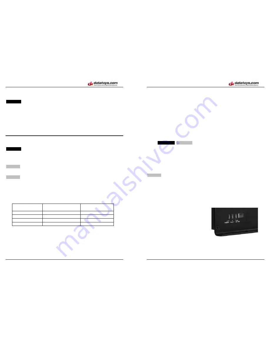
After powering on the system the unit will take 20-30 seconds to boot. Once 

booted unit will then enter one of two states indicated by the amber active light;  


Ready:


Slow Blink, 1500ms/ 


Recording:

   Fast Blink, 500ms/ 


The state is dependant upon the switch 

input and alarm settings in the DVR menu. To 
configure switch settings please see page 23.  
 

If your DVR is configured to record on power up, the unit should automatically 

begin recording when no switch is connected. To stop the recording you may simply 
cut power to the XM-DVR Pro. When power is cut the unit will automatically close the 
file from the last archive point. 

Summary of Contents for XM-DVR Pro

Page 1: ...ctions 8 DVR Connections 9 DVI Connections 10 Recorder Installation 11 Power Supply Installation 12 Camera Installation 13 Cable Installation 13 Using the System 14 Before you begin 14 Recording 14 Re...

Page 2: ...All components must be checked for safe and secure mounting before each use WARNING Before connecting the XM DVR Pro to a power source all batteries and power supplies must be disconnected All engines...

Page 3: ...XM DVR Pro can also playback all files through the standard RCA AV OUT using the infrared remote control The XM DVR Pro configuration and setup is performed through the menu that is accessible throug...

Page 4: ...with patch cable audio input cable or microphone MIC 2 Mates with patch cable audio input cable or microphone XM DVR Pro Dual Channel DVR Page 8 of 32 December 2009 Manual Rev 3 05 Installation CAUTI...

Page 5: ...the form of a female 4 PIN connector This connection mates with Datatoys cameras and extension cables Adapter cables are available at www datatoys com for use with non Datatoys cameras Audio Connecti...

Page 6: ...can be mounted in any orientation while maintaining access to the media bays and clearance for connections XM DVR Pro Dual Channel DVR Page 12 of 32 December 2009 Manual Rev 3 05 Power Supply Installa...

Page 7: ...I RF emitting line their intersection should perpendicular to one another Once cabling and all other components are installed connect the system per the connection instructions on page 8 XM DVR Pro Du...

Page 8: ...universal RCA type connection First connect the 4 PIN connection of the AV OUT cable to the AV OUT connection on the DVI harness The AV OUT lead is located on the DVI harness which connects to the bac...

Page 9: ...insert the compact flash card and boot the DVR Once the DVR is fully booted and in Ready Mode you may connect the DVR to your PC using the included USB2 0 cable Your PC should automatically recognize...

Page 10: ...require pressing the Function key then the appropriate button Button Function Enter Capture JPEG Bookmarks BWD JMP or F1 Jump 5 minutes back in current video FWD JMP or F3 Jump 5 minutes forward in cu...

Page 11: ...Clock time and date setting Zones camera area name setting Storage provides hard disk properties and setting of data overwriting mode Password operator password setting OSD On Screen Display properti...

Page 12: ...itch is closed o N C normally closed events are triggered when switch is open Trigger 1 4 assigns individual triggers to specific channels XM DVR Pro Dual Channel DVR Page 24 of 32 December 2009 Manua...

Page 13: ...ight arrow XM DVR Pro Dual Channel DVR Page 26 of 32 December 2009 Manual Rev 3 05 OSD On Screen Display On screen display appearance settings Transparency sets transparency level Auto Hide hides lowe...

Page 14: ...ll cyclic files by channel date and time For playback controls see page 19 Plan This feature allows the ability to schedule recordings based on a specific time Press CHNL to switch between channels Ab...

Page 15: ...roblem DVR is not recording Possible Solutions Connect Cameras Connect Switch Change Switch Settings XM DVR Pro Dual Channel DVR Page 30 of 32 December 2009 Manual Rev 3 05 Accessories Datatoys offers...

Page 16: ...ject to misuse water exposure neglect incorrect installation unauthorized modification accident or has been repaired or altered outside of our factory The express warranty contained herein is in lieu...

Reviews: