Passport 2®/Passport 2 LT™ Service Manual
0070-10-0441
5 - 27
Replacement Parts
Communication Ports Parts List
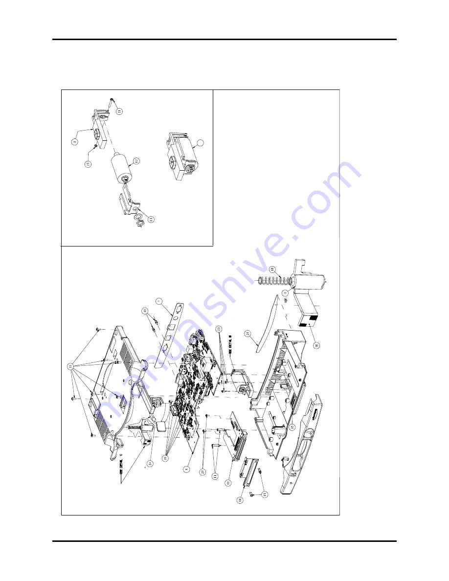
FIGURE 5-7
Base
S
tation
Asse
mbly
36
Det
ail B
Page 1: ...Service Manual Passport 2 Passport 2 TM...
Page 2: ...tered trademark of Nellcor Puritan Bennett Inc OxiMax is a U S registered trademark of Nellcor Puritan Bennett Inc Oxismart is a U S registered trademark of Nellcor Puritan Bennett Inc Passport 2 is a...
Page 3: ...LCD CRT VGA Controller U16 2 7 PCMCIA Interface 2 7 Serial EEPROM 2 7 CO Interface Connector J4 2 8 Recorder Interface 2 8 CO2 Interface Connector J23 2 8 NIBP Interface Connector J25 2 8 Defib Conne...
Page 4: ...10 2 25 Secondary Microcontroller U4 2 25 Memory 2 26 CMOS Static RAM 2 26 CMOS EEPROM 2 27 Voltage Sources 2 27 Host Reset 2 28 Patient Connector Board AAMI 2 29 Spark Gap Suppressor 2 29 Neon Bulbs...
Page 5: ...neumatic System Control 2 46 Pressure Transducer PT1 2 47 ADC U2 2 47 DAC 2 48 Pump M1 2 48 Dump Valve V1 2 48 Linear Valve V2 2 48 Over Pressure Detection 2 49 Pressure Transducer PT2 2 50 12VSW Circ...
Page 6: ...enance 7 1 Preventive Maintenance Schedule 7 2 Mechanical Physical Visual Inspection 7 2 Perform at Twelve Month Intervals 7 2 Preventive Maintenance Kit 7 2 Perform Verification and NIBP Calibration...
Page 7: ...n may have been updated to reflect product design changes and or manual improvements Any such changes to this manual would be accomplished by supplying replacement pages and instructions for inserting...
Page 8: ...Introduction Warning vi 0070 10 0441 Passport 2 Passport 2 LT Service Manual This page intentionally left blank...
Page 9: ...on 1 2 1 1 Introduction Sections 1 2 and 1 3 are intentionally left blank Please refer to the Operating Instructions for complete details OPERATING INSTRUCTIONS PART NUMBER For software version V x ea...
Page 10: ...70 10 0441 Passport 2 Passport 2 LT Service Manual 1 2 Controls Indicators And Connectors THIS SECTION LEFT INTENTIONALLY BLANK REFER TO THE OPERATING INSTRUCTIONS 1 3 Operation THIS SECTION LEFT INTE...
Page 11: ...2 6 Patient Connector Board H P 2 31 2 7 Nellcor Interface Board 2 33 2 8 Recorder Interface Board AR 42 2 33 2 9 XE 50 Recorder Interface Board 2 34 2 10 Power Supply 2 36 2 12 El Display Interface...
Page 12: ...upervisor The signal generated is active low for 140ms PORESET is generated whenever both VCC rises from 0 to 4 75 volts and the 3 3V rises from 0 to 2 75V The PORESET signal is distributed to other c...
Page 13: ...the MPC860T as well as other components that require reset is generated for both logic voltages 5V and 3 3V This keeps the CPU in reset until the power for all the digital components are above minimu...
Page 14: ...he external memory controller pins for each clock cycle Each word in the RAM array provides bits that allow a memory access to be controlled with a resolution of one quarter of the external bus clock...
Page 15: ...etween the main processor MPC860T U2 and the communication processor MCF5282 U22 Refer to the Module Bus Protocol Specification See Appendix The implementation uses the interrupt function There are tw...
Page 16: ...hot swappable is powered up with a Passport 2 monitor the module ID is read by software and is in the flow of the start up code This reading of the module ID upon power up is automatic and is not dep...
Page 17: ...rious display panels are routed to the Keypad Display board through connector J5 The various Keypad Display boards have specific interface connectors for each display type requiring only a simple one...
Page 18: ...ata can be sent This connector also provides an interface to the fan for control and monitoring There is a control line from the MPC860T to turn the fan on or off and a status signal that indicates if...
Page 19: ...Kelvin connection no current flow in sense lines The current limit is controlled by current sense resistor R32 2 1 24 12 Volts DC There is a limited requirement for 12 Vdc 30 ma max The supply voltag...
Page 20: ...an attenuator circuit which attenuates the battery voltage by 1 4 to stay within the limits of the A D converter 5 Vdc 2 1 28 SRAM There is 128K x 8 bytes SRAM which is used to store temporary variab...
Page 21: ...a RS 485 module bus The Communications processor is the host and all modules are slave devices The Communications Processor UART connects to the module bus through RS 485 buffer driver U20 The directi...
Page 22: ...it voltage of a defibrillator up to 5 kV Further it requires low capacitance between the input and output to minimize leakage currents which may flow should the patient accidently contact line voltage...
Page 23: ...set as outputs and disabled This is performed by programming all the unused general purpose I O pins as outputs at initial software boot up This also helps reduce power dissipation The other default v...
Page 24: ...ical blocks under the control of software routines executing out of another pair Some of the requirements satisfied by the design are 8KB SRAM and 96KB Flash EEPROM The SRAM is used for the BOOT RAM s...
Page 25: ...6 4 QA 4 Ports EL EH and AS 5 2 are used for microprocessor control signals and are configured as outputs except for Port EH bit 1 which is an input The table below shows the bit assignments for the...
Page 26: ...wo ECG lead select bits LS0 and LS1 2 2 9 Lead Fault Detection Lead fault detection is performed by observing the voltage on the ECG amplifier inputs Due to the bias networks included in the lead buff...
Page 27: ...ontent signal U212 provides rejection of the Respiration excitation carrier but permits passage of pacer signals Positive and negative input pins of this comparator are biased near half of the 5 rail...
Page 28: ...lter is set to 0 155 Hz which produces a 0 2 Hz 3 dB point when cascaded with the analog filter A Mathcad document fully documents the digital filter Note that these filters are based on the 100Hz sam...
Page 29: ...when a 400 series probe or no probe is present 2 2 14 Timers The only digital input to the processor is Timer Input Compare 1 Port GP 0 which is used for pacer detection This line exhibits a falling...
Page 30: ...aracter Software must rapidly evaluate this character to determine if it matches the module address If it does not match the SCI mode remains unchanged and the bus continues to be monitored for addres...
Page 31: ...e communications processor is set as the master device and the CPLD can only be a slave The method used to scan the keypad which is a 4 row J11 with up to 8 columns J10 is a walking zero pattern This...
Page 32: ...0KPG BP pressure transducer are used to monitor the cuff pressure redundantly for safety purposes This document describes the details of the actual design implementation developed to meet the specific...
Page 33: ...placed and as part of the yearly service routine for the NIBP module The BP provides a high level output signal which eliminates the need for an external amplifier circuit All that is required is a pu...
Page 34: ...2 4 7 Linear Valve V2 The bleed valve V2 provides bleed down of the cuff pressure The HC16Z1 software maintains the pressure bleed rate at a nominal 6mmHg per second for product specified volumes and...
Page 35: ...d valves is such that they are disabled pump off valves open The HC16Z1 has an internal ADC which will be used to monitor both pressure transducer outputs a 2 5V reference source A5V 12V and the switc...
Page 36: ...g stuck in the sleep state 2 4 10 Memory Flash Memory The program code will be stored in an Intel 28F400B5 4Mbit flash memory The flash device specified has the boot sector located at the bottom of th...
Page 37: ...using a Maxim MAX6125 2 5V reference U11 VCC can alternately be applied through J7 during in circuit programming or debugging procedures VCC shall not be applied to both connectors simultaneously VPP...
Page 38: ...This resistor s value was chosen in order to meet the RST timing requirements of the HC16Z1 If the RST rise time is too slow the HC16Z1 will assume there is an external reset and repeatedly drive RST...
Page 39: ...temperature probe connects to a three circuit phone jack connector on the Patient Connector board The temperature circuit provides high precision measurements of the thermistor resistance while using...
Page 40: ...e connectors IBP1 and IBP2 The Connector board collects all of the individual patient cables into a single ribbon cable then passes the signals to the main board 2 5 8 0670 00 0682 02 This module is r...
Page 41: ...temperature probe connects to a three circuit phone jack connector on the Patient Connector board The temperature circuit provides high precision measurements of the thermistor resistance while using...
Page 42: ...connectors IBP1 and IBP2 The Connector board collects all of the individual patient cables into a single ribbon cable then passes the signals to the main board 2 6 8 0670 00 0680 02 This module is re...
Page 43: ...oad is digital logic the current peaks are minimal The power filtering for the recorder motor and print head is provided by this board It is this board that must suppress the high current peaks from a...
Page 44: ...If the device is not in Shutdown mode and pulses are not appearing at the SENSE input a fault exists The Sense Network shall scale down the pulses that will meet the requirements of the TC646 of 90mV...
Page 45: ...terminal regulator which derives 5V from the incoming 12V 12V2 The regulated 5V is referenced to the 12V return in order to minimize the introduction motor noise generated by the fan Q2 Q3 and Q5 iso...
Page 46: ...r up A dedicated voltage reference device U801 is used as the 2 5V reference voltage for the A D converter and other parts in the frontend The tolerance of this regulator 0 1 is fairly good In the cas...
Page 47: ...argers are capable of rapid charging up to two Sealed Lead Acid or Lithium Ion batteries The chargers will be activated when AC or DS DC power is applied The power supply constantly monitors various a...
Page 48: ...ic 0 if there is a charger fault such as open shorted cell s The BATT CHARGE output is capable of driving an external LED sourcing a minimum of 10mA During BATTERY operation i e AC and DS DC powers ar...
Page 49: ...rocontroller s UART transmit data output switches driver transistor Q204 which performs an inversion while driving the LED portion of optocoupler U230 with the current being set by R328 These componen...
Page 50: ...ly be a slave Video Display Connections The J5 connector is for the EL display The EL display requires a 12V excitation voltage 5V to power the logic circuitry and can recognize the 3 3V logic levels...
Page 51: ...are connectors for the display data lines and power J14 is for the inverter Data Lines LD0 through LD7 and UD0 through UD7 originate from the video processor and are driven by 5V logic from the FCT162...
Page 52: ...roperly turn on the passive display the board employs a N Channel FET which is switched on and off by the LCDBIAS signal from the CPU board The LCDBIAS signal is connected to the CPLD for power sequen...
Page 53: ...EL2 This generates the bit pattern for the NEC 10 4 display per the following chart The 3 3V supply power to the display is filtered by a LC low pass filter made up of L4 and C64 The goal of the low p...
Page 54: ...the monostable timer is used to drive a buffer with a 3 state output which is controlled by VIDPWR In order to satisfy the input requirements of the buffer U9 the output of the monostable timer is ste...
Page 55: ...line driven low In a complete cycle each line will sequentially be driven low driving a different row on the keypad The CPLD has an 8 bit receive shift register with a latch to hold the row selection...
Page 56: ...8AC and Fujikura XFPM 050KPG BP3 pressure transducer are used to monitor the cuff pressure redundantly for safety purposes This document describes the details of the actual design implementation deve...
Page 57: ...e is wide enough to cover the 50mV transducer set point tolerance at the 150mmHg calibration pressure 2 15 3 ADC U2 The pressure signal is sampled by an Analog Devices AD7714 24 bit ADC which interfac...
Page 58: ...s maximum current flow in Q6 This corresponds to a fully closed valve Power on reset clears the DAC s output to 0 thus fully opening the valve The DAC s 2 5V reference voltage is derived from a Linear...
Page 59: ...does not warrant any heat sinking to achieve reasonable reliability 2 15 8 Over Pressure Detection There are two methods of keeping the pressure from getting too high The first method is the HC16Z1 so...
Page 60: ...exposure to moisture which may effect its performance but will be soldered in place after final assembly 2 15 10 12VSW Circuitry Q1 Q2 Disabling the pump M1 and valves V1 and V2 is accomplished by cut...
Page 61: ...h the type of measurement indicated has completed the offset reading zero and is ready for the measurement of the type encoded on STATE_OUT3 0 The over pressure signal PVO is sampled by an ADC interna...
Page 62: ...te after reset and it is virtually impossible for the flash write protocol to be reproduced due to random levels The HC16Z1 software can detect bad sector data in the flash by storing checksums which...
Page 63: ...ge and activates RST before it falls below 4 5V Since the HC16Z1 timing characteristics are specified with VCC at 5V 10 a valid VCC voltage is guaranteed while the device is out of reset The flash is...
Page 64: ...digital interface The SpO2 Interface board addresses the different power requirements as well as the different connector pin assignments for each of the three SpO2 modules The SpO2 interface board pro...
Page 65: ...step up switching power supply using a combined SEPIC and Cuk topology The switching frequency is 500KHz The choice of 15VS or 12VS is provided by using a choice of 2 different feedback resistors for...
Page 66: ...eading on general purpose inputs by the Passport front end microprocessor An ESD protection device U1 is connected to the SpO2 communications signals C1 to C4 are decoupling capacitors connected to th...
Page 67: ...pairs to the instrument The most important prerequisites for effective troubleshooting are through understanding of the instrument functions as well as understanding the theory of operation 3 2 Safety...
Page 68: ...ationary Mount Bedrail Hook Mount Visa PatientNet Radio 608 Radio Mount Bed Rail Hook Mount and 4 Screws P N 0040 00 0293 Transmitter P N 0992 00 0115 Visa I P N 0992 00 0116 Visa II Bracket Screws P...
Page 69: ...ing Stand and Wall Mount Cable Hook Assembly P N 0436 00 0132 Single Wall Mount Dimensions Track Item 19 Height Width 3 5 Arm 12 3 5 Depth Max Load per Arm lbs 80 lbs Rolling Stand Dimensions 44 Heigh...
Page 70: ...he wall mount kit on previous page for accessories when used with a Passport 2 Single Remote Color Display Wall Mount Kit P N 0020 00 0108 CRT Mounting Plate P N 0386 00 0220 Arm Mounting Plate P N 04...
Page 71: ...e Set USA Snap 18 P N 0012 00 1261 01 3 Lead Wire Set USA Snap 18 P N 0012 00 1261 07 ECG Cable Assembly 10 P N 0012 00 1255 01 Masimo Adult Ped Spo2 Kit P N 0020 00 0130 See Note 400 Series Instrumen...
Page 72: ...Safety Precautions Repair Information 3 6 0070 10 0441 Passport 2 Passport 2 LT Service Manual This page intentionally left blank...
Page 73: ...e aside from the safety risk 3 Use the Proper equipment This equipment listed below is suggested to fulfill a wide range of troubleshooting requirements It is imperative to use the designated equipmen...
Page 74: ...the Speaker cable assembly from connector J2 4 Remove the inverter cable assembly from connector J8 LCD only 5 Remove the screw that secures the LCD cable assembly cover on J3 LCD only 6 Remove the c...
Page 75: ...cor 9 Disconnect the connector J203 Panel board 10 Carefully lift the CPU board assembly from the back housing 11 Carefully angle and lift the CPU board assembly from the back housing 12 Disconnect th...
Page 76: ...using as stated in Paragraph A 2 Remove the Main frame as stated in Paragraph E 3 Remove the recorder assembly as stated in Paragraph K 4 Remove the Cable assembly from J3 5 Remove the three screws an...
Page 77: ...b to Female 15 Pin D Sub Open Ended to Female 15 Pin D Sub PART NUMBER LENGTH 0012 00 0852 01 6 feet PART NUMBER LENGTH 0012 00 0852 02 25 feet 0012 00 0852 03 50 feet 0012 00 0852 04 100 feet 0012 00...
Page 78: ...Information 3 12 0070 10 0441 Passport 2 Passport 2 LT Service Manual VGA Ext Male 15 Pin D Sub to Male 15 Pin D Sub PART NUMBER LENGTH 0012 00 0994 01 10 feet 0012 00 0994 02 25 feet 0012 00 0994 03...
Page 79: ...6 V RA LL LA RL SHIELD brown white red black green 5 X 1k 1W 5 Resistor in Connector RL LA LL RA V C R F L N brown white red black green L 4 1 2 3 4 5 6 Opposite Side black yellow green red white 1 2...
Page 80: ...0 USA 02 ESIS 10 USA 03 ESIS 20 USA 04 Non ESIS 10 International 05 Non ESIS 20 International 06 ESIS 10 International 07 ESIS 20 International 08 ANSI AAMI EC53 1995 IEC CONVENTIONAL STANDARD LEAD CO...
Page 81: ...IBP only for serial numbers TSXXXXX J5 and higher FIGURE 3 3 IABP Cable ECG IBP P N 0012 00 1650 01 Connector shell Shield drain wire BLK WHT RED AOUT1 ECG 1 AOUT2 PRESS 2 GNDA 3 AIN 4 GND 5 DOUT 6 P...
Page 82: ...ad set International 0012 00 1261 11 24 snap lead set International 0012 00 1261 12 40 snap lead set International 0012 00 1261 13 3 40 2 60 snap lead set USA 0012 00 1261 14 3 40 2 60 snap lead set I...
Page 83: ...08 24 pinch 3 lead set USA 0012 00 1262 09 40 pinch 3 lead set USA 0012 00 1262 10 18 pinch 3 lead set International 0012 00 1262 11 24 pinch 3 lead set International 0012 00 1262 12 40 pinch 3 lead s...
Page 84: ...2 Passport 2 LT Service Manual Panorama Mobility Lead Wires FIGURE 3 4 Panorama Mobility Lead Wires P N 0012 00 1503 XX DESCRIPTION DASH 24 snap 5 lead set Domestic 02 24 snap 3 lead set Domestic 05 2...
Page 85: ...12 00 1275 01 PART NUMBER LENGTH AND DESCRIPTION 0012 00 1274 01 6 feet Cat 5 Ethernet Cable 0012 00 1274 02 25 feet Cat 5 Ethernet Cable 0012 00 1274 03 50 feet Cat 5 Ethernet Cable 1 2 3 4 5 6 8 N C...
Page 86: ...o Gas Module Cable PART NUMBER LENGTH AND DESCRIPTION 0012 00 1276 01 12 inch 9 pin mini D serial to 25 pin D shell 0012 00 1276 02 72 inch 9 pin mini D serial to 25 pin D shell 2X 13 1 00 L 1 5 6 9 S...
Page 87: ...0441 3 21 Repair Information Disassembly Instructions Nurse Call Cable 3 pin circular to unterminated P N 0012 00 1277 02 cable shield cable shield 3 2 1 connector shield BLK WHT RED E1 E2 E3 E4 E7 E6...
Page 88: ...rial Port to RJ 45 Cable VISA P N 0012 00 1299 01 Serial Port to Corometrics Fetal Monitor Cable P N 0012 00 1300 01 P1 1 2 3 4 5 6 9 P2 1 2 3 5 6 9 Connector shield Cable shield N C N C N C N C N C 4...
Page 89: ...structions 26 pin Molex to Mini Din Cable DPD sync Cable PART NUMBER LENGTH 0012 00 1301 01 8 inches 1 inch 0012 00 1301 02 10 feet 6 inches P1 P2 1 26 25 2 L P2 P1 7 6 5 4 3 2 1 8 9 10 11 12 13 14 15...
Page 90: ...0398 P N 0212 12 0203 P N 0380 00 0397 Extender Cover Ecg Processor Card 12 Lead P N 0012 00 1441 02 Cable Assembly Lead Set 12 Lead AAMI ANSI P N 0012 00 1441 03 Cable Assembly Lead Set 12 Lead IEC I...
Page 91: ...0441 4 1 4 0 Assembly and Schematic Diagrams Detail Parts Lists Assembly and Schematic Drawings are available upon request Contact Customer Service 1 800 288 2121 x7130 Detail Parts Lists Assembly and...
Page 92: ...Panel PC 12 Cable P N 0012 00 1099 02 LNOP DCI Adult Sensor P N 0600 00 0047 01 Xducer Pump Optical Bench Solenoid Valve J1 Flow Flow J2 NIBP Hose NIBP Cuff J2 NIBP Spo2 Cable and Sensor ECG IBP Press...
Page 93: ...Passport 2 Passport 2 LT Service Manual 0070 10 0441 5 1 5 0 Replacement Parts 5 1 Parts List Front Housing 5 5 5 2 Parts List Rear Housing 5 15 5 3 Communication Ports Parts List 5 25...
Page 94: ...Replacement Parts 5 2 0070 10 0441 Passport 2 Passport 2 LT Service Manual NEC TFT LCD Display Assembly Monochrome Display 6A 6B 8 54 55 57 56 58 59 Isometric Drawing...
Page 95: ...13IN LB 2 PLACES 7 22 REF REF 36 14 15 4 PLACES 2 PLACES 17 ATTACH GROUND STRAP CONDUCTIVE SURFACE IS TO CONTACT RAIL GROUND STRAP IS PART OF THE KEYPAD ITEM 6 SERIAL NUMBER LABEL LOCATE APPROX AS SH...
Page 96: ...rts 5 4 0070 10 0441 Passport 2 Passport 2 LT Service Manual 46 45 47 48 49 50 52 51 53 44 6A 6B 8 START KEYPAD INSTALLATION AT ENCODER END Passive Display Isometric Drawing PASSIVE DISPLAY ASSEMBLY A...
Page 97: ...CB Interconnect Panel Bd LCD Display 0670 00 0686 13 Cable EL display to Interconnect Bd 0012 00 1005 14 EL Display Assembly 0160 00 0044 15 Screw Flat Head 0212 17 0807 16 EL Gasket 0348 00 0189 17 M...
Page 98: ...e Display 0670 00 1137 45 Cable Assembly 14 pin Passive Display 0012 00 1358 46 Display 10 4 Passive Color Passive Display 0160 00 0058 47 Cable Assembly 15 pin Passive Display 0012 00 1359 48 Bracket...
Page 99: ...RENCH SPANISH ITALIAN DUTCH JAPANESE DANISH IBP W IBP 01 03 05 07 09 11 13 15 W O IBP 02 04 06 08 10 12 14 16 Options with an asterisk are not released at this time Languages w ECG View ENGLISH GERMAN...
Page 100: ...Parts List Front Housing Replacement Parts 5 8 0070 10 0441 Passport 2 Passport 2 LT Service Manual This page intentionally left blank...
Page 101: ...ACES 15 25 17 16 SNAP FITTING UNDER CLIP 26 2 PLACES 25 25 6 PLACES 2 PLACES 1 28 24 3 PLACES 24 5 23 5 PLACES 28 43 6 PLACES 4 2 PLACES 10 10A 2 PLACES 14 2 49 18 67 45 54 11 2 PLACES 77 2 PLACES 68...
Page 102: ...Parts List Front Housing Replacement Parts 5 10 0070 10 0441 Passport 2 Passport 2 LT Service Manual FIGURE 5 2 Rear Panel Assembly Lithium Ion battery configuration...
Page 103: ...8 00 0170 XXXX 37 TO FRONT ASSEMBLY TO FRONT ASSEMBLY ISO VIEW EXPLODED SCALE 0 750 NELLCOR SPO2 11 12 30 31 25 27 2 PLACES 8 PLACES 13 32 33 18 29 3 PLACES REMOVE POLARIZING KEY 40 41 ISO VIEW EXPLOD...
Page 104: ...2 Passport 2 LT Service Manual FIGURE 5 4 Main Rear Assembly P N 0998 00 0900 XXXX ISO VIEW EXPLODED SCALE 0 750 ISO VIEW EXPLODED SCALE 0 750 Use In P N 0998 00 0900 XXXXX 79 80 81 82 83 83 84 30 33...
Page 105: ...Passport 2 Passport 2 LT Service Manual 0070 10 0441 5 13 Replacement Parts Parts List Front Housing FIGURE 5 5 Rear View Lithium Ion battery configuration...
Page 106: ...Parts List Front Housing Replacement Parts 5 14 0070 10 0441 Passport 2 Passport 2 LT Service Manual This page intentionally left blank...
Page 107: ...670 00 0739 01 12b PCB Main CPU Board 12 lead option 0670 00 0739 03 12c PCB Main CPU Board use with S N TS XXXX J5 or higher 0670 00 0782 03 13 Cable Interconnect Panel Bd to Main CPU Bd 0012 00 1210...
Page 108: ...LA 0014 00 0251 40 Button PCMCIA Slot B 41 Cable CO2 Module to Main CPU Bd MediCO2 0012 00 1200 41 Cable CO2 Module to Main CPU Bd miniMediCO2 0012 00 1683 01 NS Double Sided Tape 0215 00 0115 42 Scre...
Page 109: ...ware Part Number N A 67 Label Loading Recorder Paper AR 42 0334 00 1431 67 Label Loading Recorder Paper XE 50 0334 00 2674 68 Bracket Plastic Slotted MediCO2 0406 00 0805 68 Bracket Plastic Lower mini...
Page 110: ...031 041 051 MASIMO 002 012 022 032 042 052 NELLCOR OXIMAX NELL3 101 111 121 131 141 151 W O CO2 NELLCOR 003 013 023 023 003 053 MASIMO 004 014 024 024 004 054 NELLCOR OXIMAX NELL3 103 113 123 123 103...
Page 111: ...XXX Example Unit P N 0998 00 0170 0002A S W P N 0996 00 0045 002 CPU P N 0670 00 0674E02 Serial Number CM12233 K1 0001 0002 0003 0004 0005 0006 0020 0019 0018 0017 0033 0049 0050 0021 0022 0051 0052 0...
Page 112: ...Parts List Rear Housing Replacement Parts 5 20 0070 10 0441 Passport 2 Passport 2 LT Service Manual...
Page 113: ...Passport 2 Passport 2 LT Service Manual 0070 10 0441 5 21 Replacement Parts Parts List Rear Housing 1 16 4 17 2 3 18 5 6 0998 00 0178 05 RD1 NC1 SP1...
Page 114: ...Parts List Rear Housing Replacement Parts 5 22 0070 10 0441 Passport 2 Passport 2 LT Service Manual 1 19 4 17 2 3 20 5 6 0998 00 0178 06 SP1 NC1 SP2...
Page 115: ...Passport 2 Passport 2 LT Service Manual 0070 10 0441 5 23 Replacement Parts Parts List Rear Housing 1 4 2 3 5 6 15 14 13 0998 00 0178 03 CS1 MB1 RD1...
Page 116: ...Parts List Rear Housing Replacement Parts 5 24 0070 10 0441 Passport 2 Passport 2 LT Service Manual 12 11 14 4 3 1 2 6 5...
Page 117: ...ng Connector 0132 00 0077 5 Label Information 0334 00 1533 6 Label N A 7 TBD 8 TBD 9 TBD 10 TBD 11 Label CS1 MB1 RD1 Comm Port 0334 00 1541 12 PCB Assy Comm Port CS1 MB1 SP1 0670 00 0684 01 13 PCB Ass...
Page 118: ...Communication Ports Parts List Replacement Parts 5 26 0070 10 0441 Passport 2 Passport 2 LT Service Manual FIGURE 5 6 Base Station 35...
Page 119: ...Passport 2 Passport 2 LT Service Manual 0070 10 0441 5 27 Replacement Parts Communication Ports Parts List FIGURE 5 7 Base Station Assembly 36 Detail B...
Page 120: ...0008 00 0321 17 Spring Extension 375 Dia 1 5 Length 0214 00 0235 18 Spring Compression 296 Dia 1 281 Length 0214 00 0234 19 Socket Guide Docking Connector 0132 00 0077 20 Screw Pan Hd 4 40 x 25 Lg 02...
Page 121: ...6 3 6 4 2 Keypad Control Knob Test 6 4 6 4 3 Recorder Test 6 5 6 4 4 Display Tests 6 6 6 4 5 Pixel Test 6 6 6 4 6 Color Test 6 7 6 4 7 NIBP Tests 6 8 6 5 Verification 6 17 6 5 1 Initial Set up 6 17 6...
Page 122: ...are removed observe these following warnings and general guidelines 1 Do not short component leads together 2 Perform all steps in the exact order given 3 Use extreme care when reaching inside the ope...
Page 123: ...ff 2 Press and hold the FREEZE key and turn the unit on The Diagnostics Main Menu will appear on screen Release the FREEZE key 3 Rotate the Control Knob to move the cursor up and down to the Diagnosti...
Page 124: ...me window 3 Exercise each key to verify proper operation 4 A second window with blank boxes will be displayed on screen 5 When rotating the control knob the blank boxes will illuminate with each activ...
Page 125: ...6 5 Calibration Procedure Diagnostics 6 4 3 Recorder Test Select the Chart Grid ASCII Characters menu The printer will print the Recorder Test pattern as shown in Figure 1 or Figure 2 FIGURE 6 4 FIGU...
Page 126: ...vailable on units with a color display FIGURE 6 7 6 4 5 Pixel Test The pixel test will verify the proper operation the display On screen one half of the screen will be illuminated while the second hal...
Page 127: ...bration Procedure Diagnostics 6 4 6 Color Test The color test will verify the four basic colors of the display Press the control knob to view the selected color screens in full illumination The colors...
Page 128: ...ocedure a Turn Unit off Remove the eight screws that secure the front and rear housing together Separate the front and rear housing Disconnect the interconnect cable from the TFT display board and rem...
Page 129: ...on screen the Overpressure Voltage is 0 100 volts FIGURE 6 11 j Reassemble unit and verify proper operation B Specification with P N 0670 00 0730 0670 00 0746 01 No manual adjustment is required The...
Page 130: ...he chamber to 150mmHg 150mmHg is the middle of the specified range 4 Verify the pressure displayed on screen matches the pressure viewed on a Digital Mercury Manometer Specification 0 to 300mmHg 3mmHg...
Page 131: ...30 mmHg 100 mmHg 150 mmHg 190 mmHg and 250 mmHg 3 mmHg 150 mmHg Digital Mercury Manometer Bulb 693cc Test Chamber P N 0138 00 0001 01 T Fitting Overpressure Voltage Setpoint Static Pressure Calibrati...
Page 132: ...trol knob to highlight the motor pump test Once the motor pump test is highlighted press the control knob to activate the test 3 On screen the target pressure of 300mmHg will be view on screen The tim...
Page 133: ...ed press the control knob to activate the test 3 The chamber will inflated to 250 150 or 50 mmHg of pressure After ten seconds the pressure on screen the pressure is released During this ten second pe...
Page 134: ...tivate the test 3 The chamber will inflate to 270mmHg of pressure Adult 170mmHg Neonate The dump valve will start to deflate at 260 Adult 150 Neonate after 10 seconds Adult 5 seconds Neonate the unit...
Page 135: ...he side panel fitting 2 Rotate the control knob to highlight the bleed rate Once the bleed rate test is highlighted press the control knob to activate the test 3 The chamber will inflate to 220mmHg of...
Page 136: ...ontrol knob to highlight the specified overpressure test Once the overpressure test is highlighted press the control knob to activate the test NOTE Due to safety conditions the unit must be reset afte...
Page 137: ...the Passport 2 as follows Patient Menu Adult mode patient size Monitor Setup a Display Setup 3 Waveforms 6 Waveforms 12Leads b ECG Speed 25 mm sec c IBP Speed 25mm sec optional d Respiration Gas Spee...
Page 138: ...100 N20 Scale 10 6 5 2 ECG Tests 6 5 2 1 Initialization 1 Observe that the trace display sweeps across the waveform 1 screen in five seconds There should be five complete ECG cycles The same display a...
Page 139: ...CG QRS waveform Set the rate to 251 bpm 2 Verify the Rate display is 251 5 bpm 3 Decrease the rate to 30 bpm and allow signal to stabilize Verify that the rate display is 30 bpm 3 bpm E C G S T C O 2...
Page 140: ...icating the High HR was violated 6 5 3 IBP 1 and IBP 2 Verification 1 Set the simulator to 0 mmHg for both IBP 1 and IBP2 2 Press the ZERO ALL key Verify the Systolic diastolic and mean displays 0 1 m...
Page 141: ...the unit still operates Verify the second battery operates in the same manner by reinstalling the first battery and removing the second battery 6 5 8 CO2 Operation Verification 1 Connect the Filterlin...
Page 142: ...e on leads 2 Connect the ground wire from the safety analyzer to the equipotential lug of the monitor 3 Connect the ECG cable from the Analyzer to the monitor 4 On the safety analyzer depress the Appl...
Page 143: ...7 7 Care And Cleaning Of The Monitor 7 3 7 8 Care and Cleaning of SpO2 Sensor 7 3 7 9 Cleaning CO2 Sensors Adapters And Sampling Components 7 3 7 10 Sterilization and Cleaning of Reusable Cuffs 7 4 7...
Page 144: ...ation Annually 1 See section 6 5 Verification 7 5 Perform Verification and CO2 Calibration Annually 1 See Test Outline in Service Manual 2 In order to provide accuracy verification of the Microstream...
Page 145: ...oft cloth DO NOT wipe a dry screen or use alcohol or chlorinated hydrocarbon solvents 7 8 Care and Cleaning of SpO2 Sensor NOTE Refer to the individual instruction sheets packaged with each sensor 1 C...
Page 146: ...button located on the right side of the installed battery This will eject the battery Slide out old battery 3 Slide in replacement battery until it clicks into place 4 Close battery compartment door...
Page 147: ...hes If the paper jams open the door and return to step 5 7 13 Care and Storage of Thermal Chart Paper Thermal Chart Paper is chemically treated and the permanency of a recording is affected by storage...
Page 148: ...tinue to exist contact the Service Department 800 288 2121 for assistance in determining the nearest field service location Please include the instrument model number software part numbers the serial...
Page 149: ...ial Systolic Blood Pressure Measurements CVP pg 40 44 August September 1978 Hanning C D Oximetry and Anesthetic Practice Pre Operative Intra Operative Post Operative and Critical Care Ohmeda BOC Healt...
Page 150: ...m CCE Apnea Monitoring Basics Biomedical Instrumentation and Technology July August 1991 Toledo Laura Worthington Pulse Oximetry Clinical Implications in the PACU Journal of Post Anesthesia Nursing 2...
Page 151: ...gent employee or representative of Mindray DS USA Inc has any authority to bind Mindray DS USA Inc to any affirmation representation or warranty concerning its products and any affirmation representat...
Page 152: ...employee or representative of Mindray DS USA Inc has any authority to bind Mindray DS USA Inc to any affirmation representation or warranty concerning its products and any affirmation representation...
Page 153: ...ions for use 7 18 Extended Warranty Mindray DS USA Inc warrants that components within the monitor unit will be free from defects in workmanship and materials for the number of years shown on the invo...
Page 154: ...Printed in U S A 0070 10 0441 Rev AG December 1 2008...
Page 155: ...at 8 3871 An Hoevelaken The Netherlands Tel 31 33 25 44 911 Fax 31 33 25 37 621 Mindray Medical Germany GmbH Fabrikstrasse 35 64625 Bensheim Germany Tel 06251 17050 Fax 06251 67877 Mindray UK Limited...