


iBoot-30A
Page 4
iBoot-30a_v101118e
Connect 10/100 Ethernet
Hardware Installation
Ethernet Connections
iB-30 supports 10/100 Ethernet using the cord supplied, or other
suitable unshielded twisted pair (Cat 5) cabling. Remove the cover
of the metal box. Select one of the small knockouts and open it up
by prying itwith a screw driver or similar tool. A hammer may be
necessary to tap the metal insert out if it does not pry out easily.
After opening the knockout install the small cable clamp provided
and pass the network cable thru it. Plug the cable into the modular
jack provided on the network interface and control module. The Link
(amber) and Activity (green) LEDs on the network connector indicate when
the network connection is properly established.
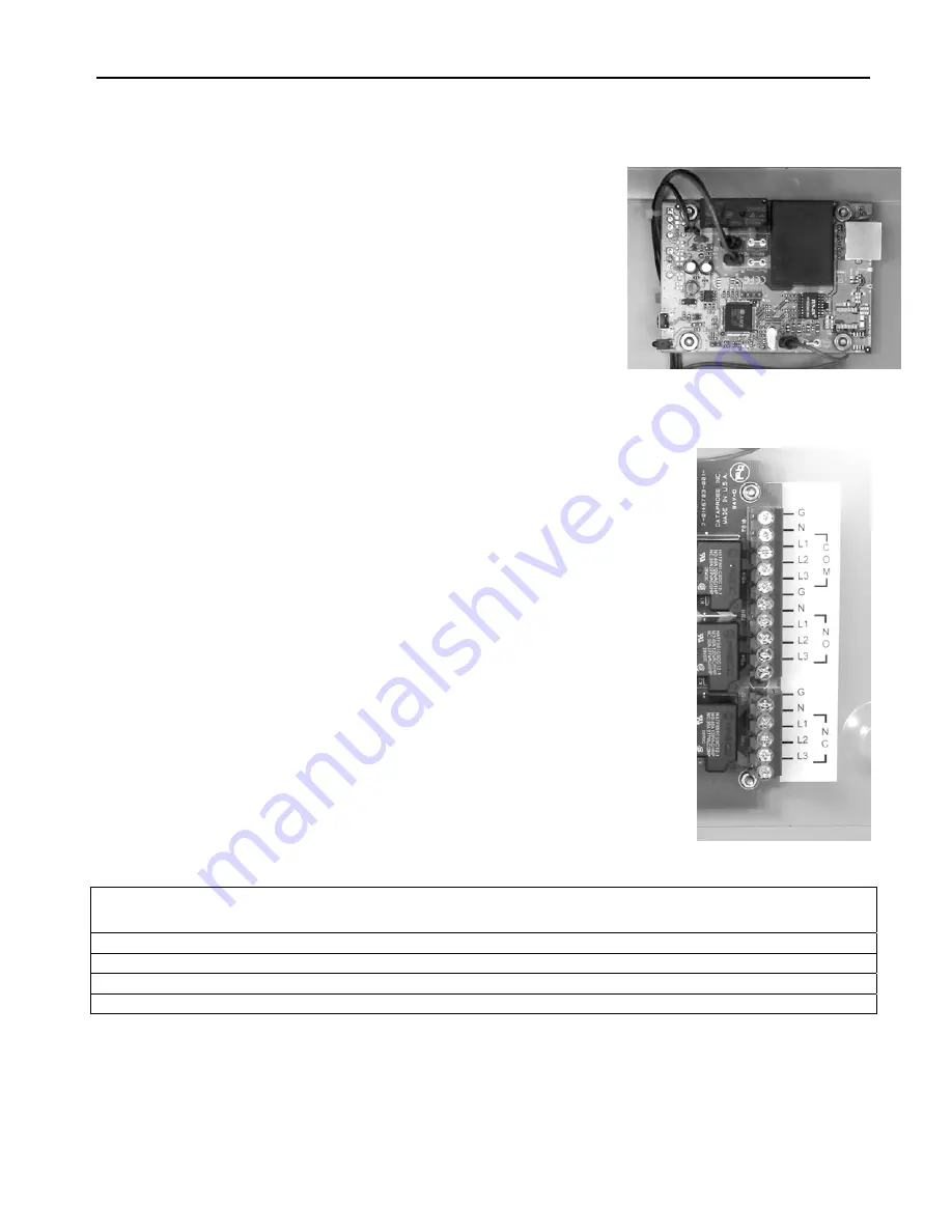
AC Power Connections
AC power connections enter the unit by selecting one or two of the
larger knockouts, similar to those used for the above network
connection, and installing the larger cable clamps.
All AC connections are made on the power relay board using the large
screw terminal blocks. Screw terminals are provided for Ground (G),
Neutral (N) for the AC input, or Common relay contact of the relay
switch as well as each output, Normally Open (N.O.) and Normally
Closed (N.C.) The Ground and Neutral wiring is not switched. Screw
terminals are also provided for the Line side and labeled; L1, L2, and
L3. L1 is used for switching single wire 120VAC or single wire 240
VAC. ( Europe) . L1 & L2 are used for two wire 220- 240VAC , and L1,
L2 & L3 are used for 3 phase wiring applications. Only 120/240V 3
phase units will have all three relays in place as shown in the picture.
Voltage Gnd Neutral L1 L2 L3
110 VAC Green White Black
220 VAC Euro Grn/Yel Blue Brown
240VAC 2Phase Green White Black
120/240VAC 3Phase Green Black Red Blue
Ethernet


