5
Rear View
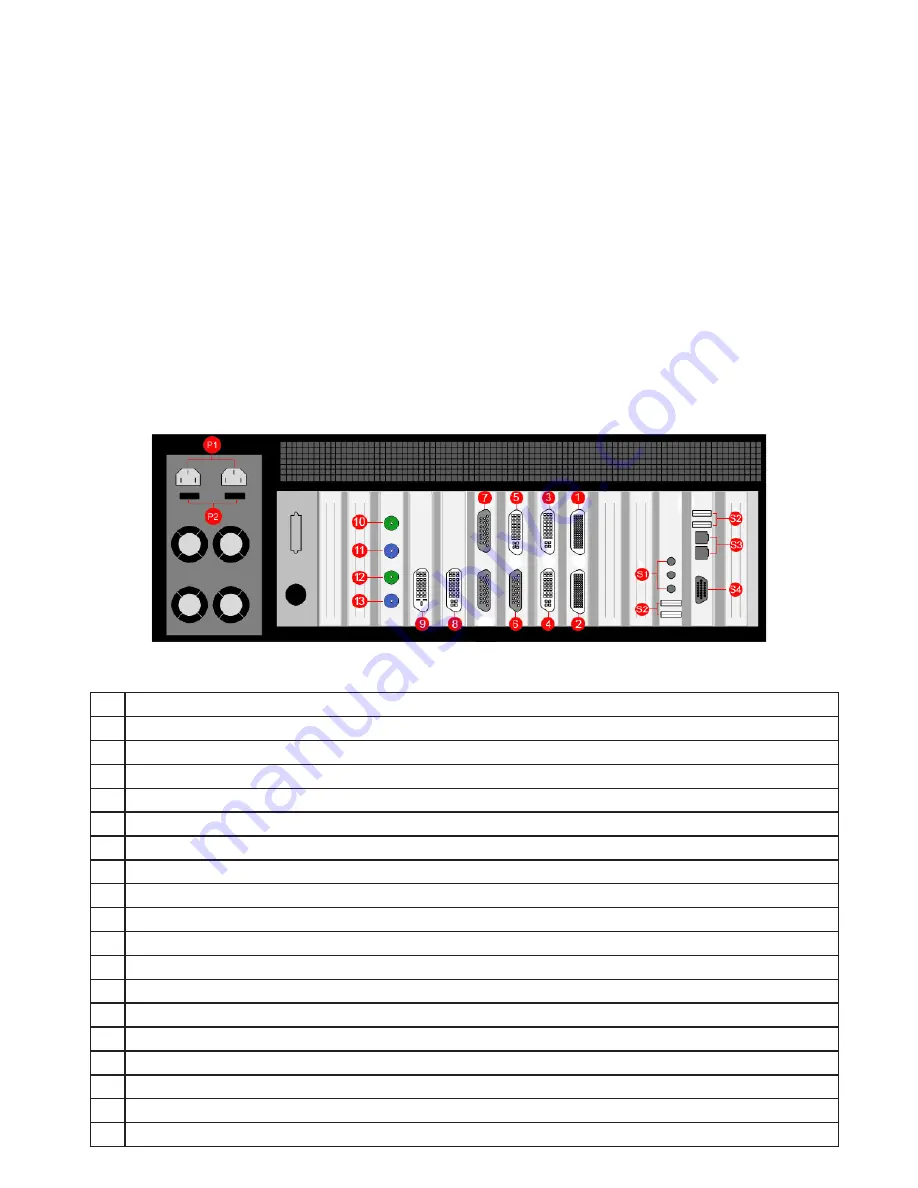
Each custom configured Vision800 will differ depending on the number of output cards and capture cards
installed. The illustration below (
Fig.3
) is an example of the rear panel and shows the six types of card that
may be installed in the Vision800:
•
Image4 card (outputs
1
and
2
)
•
VisionRGB-E2S card (inputs
3
and
4
)
•
Vi1S card (inputs
5
and
6
)
•
VisionSD8 card (input
7
)
• VisionRGB-E1S (inputs
8
)
•
VisionDVI-DL card (input
9
)
•
VisionSDI2 card Input (inputs
10
and
12
)
In this example the configuration would support a four screen display wall, (
1
and
2
) four RGB/HD/HDMI/
DVI sources (
3, 4, 5
and
8
) and a total of twelve SD Composite or S-Video sources, four into the 4 Channel
SD plus 1 DVI Capture card (
6
) and eight into the VisionSD8 card (
7
), one DVI Dual-Link source (
9
) and two
SD-SDI/HD-SDI/3g-SDI sources (
10
and
12
).
Fig.3 (Model shown - RPSU)
P1
Power Connectors. (Only one power connector for the ATX model.)
P2
Main Power Switches. (Only one main power switch on the ATX model.)
1
Image4 graphics card output connector - For connecting output cables (
Fig.4
)
2
Image4 graphics card output connector - For connecting output cables (
Fig.4
)
3
VisionRGB-E2S capture card DVI-I Input connector = RGB/HD/HDMI/DVI source. (
Fig.5/6/7/8
)
4
VisionRGB-E2S capture card DVI-I Input connector = RGB/HD/HDMI/DVI source. (
Fig.5/6/7/8
)
5
Vi1S capture card DVI-I Input connector – = RGB/HD/HDMI/DVI source. (
Fig.5/6/7/8
)
6
Vi1S capture card D-Type Input connector = SD Composite/S-Video sources. (
Fig.11
)
7
VisionSD8 capture card D-Type Input connector = SD Composite/S-Video sources. (
Fig.12
)
8
VisionRGB-E1S capture card DVI-I Input connector = RGB/HD/HDMI/DVI source. (
Fig.5/6/7/8
)
9
VisionDVI-DL capture card Dual Link DVI-D Input connector = Dual Link DVI source. (
Fig.9
)
10
VisionSDI2 capture card BNC Input connector 1 = SD-SDI/HD-SDI/3G-SDI sources. (
Fig.10
)
11
VisionSDI2 Capture card BNC Passthrough connector for input connector 1. (
Fig.10
)
12
VisionSDI2 capture card BNC Input connector 2 = SD-SDI/HD-SDI/3G-SDI sources. (
Fig.10
)
13
VisionSDI2 Capture card BNC Passthrough connector for input connector 2. (
Fig.10
)
S1
Aux Inputs connectors.
S2
USB Input connectors.
S3
Network connectors.
S4
VGA Output connector for the Control Screen
Key


