background image

Model 2200 Printer


OPERATION AND MAINTENANCE


DataMetrics Corporation 

18 


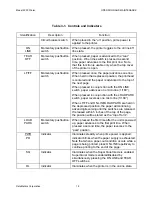
Table 3-1.  Controls and Indicators 


Identification Description 

Function 


Circuit breaker switch 

When placed in the “on” position, prime power is 
applied to the printer. 

ON 

LINE 

Momentary pushbutton 
switch 

When pressed, the printer toggles to the on line/off 
line state.  

TEAR 

OFF 

Momentary pushbutton 
switch 

When pressed, paper is advanced to the “tear” 
position.  When the switch is pressed a second 
time, paper advances to the first print line.  Note 
that this function is usable only when the top cover 
of the printer is open. 

LF/FF Momentary 

pushbutton 

switch 

When pressed once, the paper advances one line. 
When held in the depressed position, the printhead 
is centered and the paper is advanced to the top of 
the next page. 

When pressed in conjunction with the ON LINE 
switch, paper advances one micro line (1/180”).  

When pressed in conjunction with the LOAD PARK 
switch, paper reverses one micro line (1/180”). 

When LF/FF and ON LINE/LOAD PARK are held in 
the depressed position, the paper will continuing 
advancing/reversing until the switches are released.  
If released within 5 inches of the top of the page, 
the position will be stored as the “top of form”. 

LOAD 
PARK 

Momentary pushbutton 
switch 

When pressed the first time after the unit is powered 
up, paper advances to the first print line.  When 
pressed a second time, the paper reverses to the 
“park” position. 

PWR 

PO 

Indicator 

Illuminates steadily when prime power is applied; 
indicator blinks when the paper supply is exhausted.  
Note that when a paper-out condition occurs while a 
page is being printed, press ON LINE repetitively to 
continue printing to the end of the page. 

SQ 

Indicator 

Illuminates when the Super Quiet mode is enabled.  
Super Quiet mode is enabled/disabled by 
simultaneously pressing the ON LINE and TEAR 
OFF switches. 

OL 

Indicator 

Illuminates when the printer is in the on-line state. 


Summary of Contents for 2200

Page 1: ...rlando Fl 32809 This manual is intended to function as an example ONLY and does not represent all configurations and options for this product Model 2200 Dot Matrix Printer 24 VDC 110 220VAC with Parallel Interface Operation and Maintenance Manual ...

Page 2: ... FOR PREPARING THE SAME OR SIMILAR COMPUTER SOFTWARE OR C USED BY A PARTY OTHER THAN THE GOVERNMENT EXCEPT FOR 1 EMERGENCY REPAIR OR OVERHAUL WORK ONLY BY OR FOR THE GOVERNMENT WHERE THE ITEM OR PROCESS CONCERNED IS NOT OTHERWISE REASONABLY AVAILABLE TO ENABLE TIMELY PERFORMANCE OF THE WORK PROVIDED THAT THE RELEASE OR DISCLOSURE HEREOF OUTSIDE THE GOVERNMENT SHALL BE MADE SUBJECT TO A PROHIBITION...

Page 3: ...Model 2200 Printer OPERATION AND MAINTENANCE DataMetrics Corporation i RECORD OF CHANGES Date Revision Description of Change 040818 INITIAL RELEASE ...

Page 4: ...5 2 2 Chassis Installation Configuration 5 2 3 Unpacking 5 2 4 Ribbon Installation 5 2 5 Paper Installation 5 2 6 External Cable Installation 6 2 7 Software Installation 6 2 8 Setup Utility 7 2 9 Limited Operation Storage and Transportation 10 3 OPERATION 16 3 1 Introduction 16 3 2 Controls and Indicators 16 3 3 Self Test 19 3 3 1 Printer 19 3 4 Normal Operation 19 3 4 1 Stopping a Print Job 19 3 ...

Page 5: ... Cleaning and Lubrication 22 5 3 2 Ribbon Cassette Re Inking 22 5 4 Fault Isolation 22 5 5 Replaceable Components and Subassemblies 25 5 5 1 Ribbon Cassette 27 5 5 2 Print Engine 27 5 5 3 Power Supply 28 5 5 4 Circuit Breaker Assembly 28 5 5 5 Transient Protection Circuit 29 5 5 6 EMI Filter 30 5 5 7 Controller Board 30 5 5 8 Control Panel Interface 31 5 5 9 Control Panel 31 ...

Page 6: ...e 4 1 Chassis Interconnections 21 Figure 5 1 Periodic Maintenance Locations 23 Figure 5 2 Replaceable Unit Locations 26 Tables Table 1 1 Physical Specifications 2 Table 1 2 Electrical Specifications 3 Table 1 3 Environmental Specifications 3 Table 1 4 Printer Performance Specifications 4 Table 2 1 Setup Utility Menus 8 Table 2 2 Setup Utility Function Keys 10 Table 2 3 External Connectors 15 Table...

Page 7: ...al management techniques that protect internal components from shock vibration temperature extremes and EMI RFI The chassis is configured with a mechanically isolated vehicle mounting adapter The printer includes the following primary functional elements Power subsystem Printing subsystem Control panel Ethernet subsystem External interfaces 1 3 1 Power Subsystem The Model 2200 Dot Matrix Printer o...

Page 8: ...d from the host computer Controls and indicators are described in Chapter 3 1 3 4 External Interfaces The rear panel of the Model 2200 Dot Matrix Printer includes connectors for prime power and the host computer data interface A chassis ground lug is located on the rear panel below the power connector The printer incorporates a Centronics parallel data interface External connector assignments are ...

Page 9: ...Idle active printing mode Table 1 3 Environmental Specifications Characteristic Description Temperature Operating Non operating 25 to 55o C 30 to 71o C Relative humidity non condensing Up to 90 Altitude operating 3 000 m Vibration operating MIL STD 810D Figure 514 3 10 through 514 3 22 Shock Non operating Operating 20 g 6 ms 15 g 6 ms EMI EMC MIL STD 461C Part 4 Methods RE02 RS03 and RS05 IEC 1000...

Page 10: ...1 horizontal x 0 14 mm vertical Letter quality 0 07 horizontal x 0 14 mm vertical Characters per inch cpi per line cpl Pica 10 cpi 80 cpl Elite 12 cpi 96 cpl Micron 15 cpi 120 cpl Compressed 17 cpi 137 cpl Elite compressed 20 cpi 160 cpl Pica elongated 5 cpi 40 cpl Elite elongated 6 cpi 48 cpl Micron elongated 7 5 cpi 60 cpl Compressed elongated 8 5 cpi 68 cpl Elite compressed elongated 10 cpi 80 ...

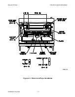
Page 11: ... bar 2 4 Ribbon Installation Follow the procedure defined below to install a ribbon cassette in the Model 2200 Dot Matrix Printer Refer to Figure 2 3 a Open the top cover of the printer and power up the unit to center the ribbon carriage b Adjust the head gap lever to the 6 position c Rotate the knob on the ribbon cassette clockwise to remove any slack d Position the ribbon cassette over the print...

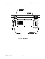
Page 12: ...ver of the printer Press and hold LF FF to advance the paper through the paper egress slot in the top cover 2 6 External Cable Installation All external interfaces for the printer are located at the rear panel Figure 2 4 External connector signal assignments are defined in Table 2 3 Perform the following steps to connect external cabling a Verify that the front panel circuit breaker is in the off ...

Page 13: ... configure operational parameters for the printer using the Setup Utility a Verify that a parallel interface cable is installed between a Windows based host computer and the parallel port of the printer b Power up the host computer and printer Verify that the printer is on line c At the Windows main screen of the host computer select Start Run d Insert the Setup disk in the diskette drive e Enter ...

Page 14: ... 5 3 4 4 5 5 6 7 5 8 9 10 and 12 lpi Page Length 5 5 8 8 5 11 11 66 12 and 14 inches Top Margin 0 to 2 5 inches Bottom Margin 0 to 5 0 inches Left Margin 0 to 78 columns 1 Right Margin 2 to 80 columns 1 Center Printhead Column 10 to 45 Print Mode Graphic Direction Bi directional or Unidirectional Text Direction Bi directional or Unidirectional Text Enhancement Bold Off On Double Height Off On Doub...

Page 15: ...l Character Set Italic Graphic1 and Graphic2 Code Page U S A Multilingual Portugal French Canadian Norway Turkey BRASCII and ABICOMP Install AGM IBM Off On Auto CR IBM Off On Auto LF Off On Auto Loading Off On Paper Out Detect Off On Super Quiet Mode Off On Tear Off Manual Auto CSF Mode Off On Download Off On Color 2 Black Magenta Cyan Violet Yellow Orange and Green Auto On Line Off On Data Length...

Page 16: ...ttings F10 Send to Printer Downloads the current menu settings to the printer ESC Exit Exit the Setup Utility 2 9 Limited Operation Storage and Transportation If the printer is not operated for an extended period of time the paper and ribbon should be removed and stored in a humidity controlled environment This provision is particularly important when the equipment is used in a high humidity envir...

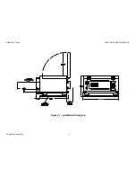
Page 17: ...Model 2200 Printer OPERATION AND MAINTENANCE DataMetrics Corporation 11 A D E C B Figure 2 1 Installation Dimensions ...

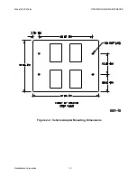
Page 18: ...Model 2200 Printer OPERATION AND MAINTENANCE DataMetrics Corporation 12 Figure 2 2 Vehicle Adapter Mounting Dimensions ...

Page 19: ...Model 2200 Printer OPERATION AND MAINTENANCE DataMetrics Corporation 13 Figure 2 3 Ribbon and Paper Installation ...

Page 20: ...Model 2200 Printer OPERATION AND MAINTENANCE DataMetrics Corporation 14 E D B C A Figure 2 4 Rear Panel ...

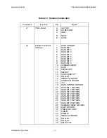
Page 21: ... 25 26 27 28 29 30 31 32 33 34 35 36 DATA STROBE DATA BIT 1 DATA BIT 2 DATA BIT 3 DATA BIT 4 DATA BIT 5 DATA BIT 6 DATA BIT 7 DATA BIT 8 ACKNOWLEDGE BUSY PAPER OUT SELECT AUTO FEED XT Not used SIGNAL GROUND CHASSIS GROUND 5V DATA STROBE RETURN DATA BIT 1 RETURN DATA BIT 2 RETURN DATA BIT 3 RETURN DATA BIT 4 RETURN DATA BIT 5 RETURN DATA BIT 6 RETURN DATA BIT 7 RETURN DATA BIT 8 RETURN ACKNOWLEDGE ...

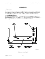
Page 22: ...wn Before the unit is powered up for the first time verify that the installation procedures defined in Chapter 2 have been performed 3 2 Controls and Indicators All controls and indicators required for operation of the Model 2200 Dot Matrix Printer are located at the front panel of the unit Figure 3 1 Control panel switches and indicators are shown in Figure 3 2 Controls and indicators are describ...

Page 23: ...Model 2200 Printer OPERATION AND MAINTENANCE DataMetrics Corporation 17 Figure 3 2 Control Panel ...

Page 24: ...s one micro line 1 180 When pressed in conjunction with the LOAD PARK switch paper reverses one micro line 1 180 When LF FF and ON LINE LOAD PARK are held in the depressed position the paper will continuing advancing reversing until the switches are released If released within 5 inches of the top of the page the position will be stored as the top of form LOAD PARK Momentary pushbutton switch When ...

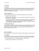
Page 25: ...lity Table 2 1 Once the printer has achieved an on line state no manual intervention is required to conduct routine print tasks Operational parameters are not affected by normal power on off cycles 3 4 1 Stopping a Print Job A print job can be terminated from the host computer or at the printer control panel Place the printer off line to stop a print job from the control panel Cycling printer powe...

Page 26: ...ower supply input connector The power supply converts 28 Vdc input to outputs of 5 V at 2 A and 39 V at 6 A Power supply outputs are provided to the controller board 12 V converter and heaters A chassis ground stud is located on the rear panel of the unit 4 1 2 Printing Subsystem The Model 2200 Dot Matrix Printer incorporates the printing architecture of the Panasonic Model KX P2130 printer The pr...

Page 27: ...Model 2200 Printer OPERATION AND MAINTENANCE DataMetrics Corporation 21 Figure 4 1 Chassis Interconnections ...

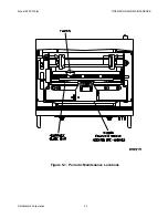
Page 28: ...ohol Vacuum dust and paper particles from the chassis interior Apply a small amount of very light oil to the carriage guide bar Figure 5 1 5 3 2 Ribbon Cassette Re Inking A black ribbon supports the printing of approximately 3 million characters in draft mode When the print image begins to fade the ribbon can be re inked Re inking is accomplished by removing the cassette and gently pushing the rib...

Page 29: ...Model 2200 Printer OPERATION AND MAINTENANCE DataMetrics Corporation 23 Figure 5 1 Periodic Maintenance Locations ...

Page 30: ...uminate when paper supply is exhausted Enable Paper Out Detect setting Table 2 1 Printer will not power up Verify that input power is 24VDC OR 110 220VAC If input power is correct verify that supply voltage is present at EMI filter input terminals If voltage is not correct replace transient protection circuit assembly If voltage at EMI filter input a terminal is correct verify that supply voltage ...

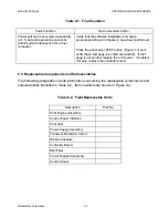
Page 31: ... and verify that a test page is printed successfully If test page is not printed replace the print server If problem remains replace the controller board 5 5 Replaceable Components and Subassemblies The following paragraphs include information concerning the replaceable components and subassemblies identified in Table 5 2 Item locations are shown in Figure 5 2 Table 5 2 Field Replaceable Units Des...

Page 32: ...Model 2200 Printer OPERATION AND MAINTENANCE DataMetrics Corporation 26 Figure 5 2 Replaceable Unit Locations Note This printer does not contain the 12VDC Converter or Ethernet Print Server ...

Page 33: ...ge down and position it under the retaining bracket Ensure that the ribbon is located between the printhead nose and the ribbon mask Gently press down on the cassette until it snaps into place c Adjust the head gap lever for the thickness of paper used 1 thin to 6 thick A head gap setting of 2 or greater is recommended for normal operation d Close the top cover of the printer and power down the un...

Page 34: ... Install the print engine assembly per 5 5 2 5 5 4 Circuit Breaker Assembly Removal a Remove the print engine assembly per 5 5 2 b Remove the three screws that secure the EMI filter transient protection circuit cover Remove the cover from the chassis c Remove the two nuts that secure the EMI filter to the inside of the chassis rear panel d Remove the DC and DC terminals of the circuit breaker harn...

Page 35: ...ble b Remove the three screws that secure the EMI filter transient protection circuit cover Remove the cover from the chassis c Remove the four screws that secure the transient protection circuit assembly to the rear panel of the chassis d Remove the DC and DC terminals of the transient protection circuit from the input top EMI filter connections Remove the protection circuit assembly from the cha...

Page 36: ...s on the EMI filter ground connection c Install the DC and DC terminals of the circuit breaker harness on the EMI filter output bottom connections d Position the EMI filter on the chassis and install the hardware that secures the filter e Install the EMI filter transient protection circuit cover f Install the print engine per 5 5 2 5 5 7 Controller Board Removal a Remove the print engine assembly ...

Page 37: ...nt engine base plate and install the hardware that secures the module b Install the control panel interface board cables c Install the print engine assembly per 5 5 2 5 5 9 Control Panel Removal a Open the top cover of the printer b Disconnect the control panel interface cable c Remove the six nuts that secure the control panel to the back of the front panel Remove the panel from the chassis Insta...

Reviews: