Model 2200 Printer
OPERATION AND MAINTENANCE
DataMetrics Corporation
iv
Figures
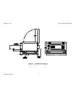
Figure 2-1. Installation Dimensions
............................................................................................... 11
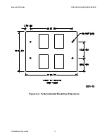
Figure 2-2. Vehicle Adapter Mounting Dimensions
..................................................................... 12
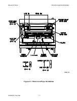
Figure 2-3. Ribbon and Paper Installation
.................................................................................... 13
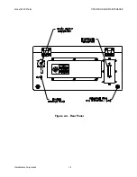
Figure 2-4. Rear Panel
.................................................................................................................... 14
Figure 3-1. Front Panel
.................................................................................................................... 16
Figure 3-2. Control Panel
................................................................................................................ 17
Figure 4-1. Chassis Interconnections ..................................................................................21
Figure 5-1. Periodic Maintenance Locations .......................................................................23
Figure 5-2. Replaceable Unit Locations ..............................................................................26
Tables
Table 1-1. Physical Specifications
................................................................................................... 2
Table 1-2. Electrical Specifications
.................................................................................................. 3
Table 1-3. Environmental Specifications
........................................................................................ 3
Table 1-4. Printer Performance Specifications
.............................................................................. 4
Table 2-1. Setup Utility Menus
......................................................................................................... 8
Table 2-2. Setup Utility Function Keys
.......................................................................................... 10
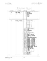
Table 2-3. External Connectors
..................................................................................................... 15
Table 3-1. Controls and Indicators
................................................................................................. 18
Table 5-1. Fault Isolation
................................................................................................................. 24
Table 5-2. Field Replaceable Units
............................................................................................... 25


