background image


Chapter 2 – Printer Setup 

To simplify the adjustment, the AMS uses Reference Letter designators that correspond to the following TOF 

mark distances:   


 Distance of the TOF Mark from the Media Edge  


Reference 

Letter 

(inches)


(millimeters)


A .180 

4.6 

B .500 

12.7 

C .750 

19.1 

D 1.00 

25.4 

E 1.25 

31.8 

F 1.50 

38.1 

G 1.75 

44.5 

H 2.00 

50.8 

I 2.25 

57.2 

J 2.50 

63.5 

K 2.75 

69.9 

L 3.00 

76.2 


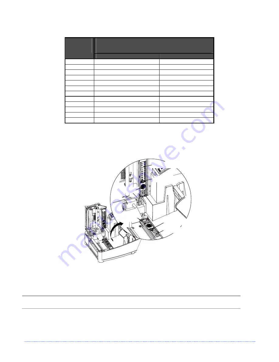
Position the Adjustable Media Sensor as follows: 


1.   Based on the measurement made earlier, choose the Reference Letter that best corresponds to the 

location of your TOF mark.  


Top Slide

Bottom Slide

Reference Letters

Reference Letters

Setting Window

Setting Window


2.  Use a finger to move the Bottom Slide until your selected Reference Letter appears in the Setting Window 

of the slide.  


3.  Use a finger to move the Top Slide until your selected Reference Letter appears in the Setting Window of 

the slide. 


The Top and Bottom Slides must be positioned over the same Reference Letter for proper media 

sensor function. 


4.  Proceed to ‘Loading Media’ (Section 2.4).  


Summary of Contents for Mark II E-4205e

Page 1: ...Operator s Manual...

Page 2: ......

Page 3: ...manual may be reproduced or transmitted in any form or by any means for any purpose other than the purchaser s personal use without the expressed written permission of Datamax O Neil Corporation All...

Page 4: ...First Edition Gost R FCC This device complies with FCC CFR 47 Part 15 Class A Note This equipment has been tested and found to comply with the limits for a Class A digital device pursuant to Part 15 o...

Page 5: ...e er r ra a at t ti i io o on n n 3 1 Introduction 11 3 2 Lights 11 3 3 Buttons 12 3 4 Printer Configuration Tools 13 3 5 Printer Configuration Utility DMXConfig 14 3 6 Windows Driver 16 3 7 Media Cal...

Page 6: ...n ns s s A A Ap p pp p pe e en n nd d di i ix x x B B B I I In n nt t te e er r rn n na a al l l M M Me e en n nu u u A A Ap p pp p pe e en n nd d di i ix x x C C C E E Et t th h he e er r rn n ne e...

Page 7: ...inter driver can be found on our website www datamax oneil com or on the included Accessories CD ROM If you wish to write a custom program a copy of the Class Series Programmer s Manual part number 88...

Page 8: ...2 Chapter 1 Getting Started...

Page 9: ...ne e ec c ct t ti i in n ng g g t t th h he e e P P Pr r ri i in n nt t te e er r r 2 2 1 Power Connection Before connecting the AC Power Cord or interface cables to the printer ensure the Power On O...

Page 10: ...serial RS 232C interface use an acceptable cable configuration as shown below contact your reseller for ordering information Part 32 2483 01 Part 32 2301 01 To connect the printer to the host s paral...

Page 11: ...r printer proceed as follows 1 Open the cover 2 Push down the Printhead Latch and raise the Printhead Carrier Assembly The Fixed Position Media Sensor shown below is immoveable If your printer has thi...

Page 12: ...Reflective Near the center of the black mark Reflective The printer must be configured to use continuous media see Section 3 4 To properly position the AMS you will need to know where the TOF mark is...

Page 13: ...s follows 1 Based on the measurement made earlier choose the Reference Letter that best corresponds to the location of your TOF mark Top Slide Bottom Slide Reference Letters Reference Letters Setting...

Page 14: ...Roll Media Printhead Latch Printhead Carrier Media Hub Media Hub Flange smooth side toward media Standoff 5 Slide the Media Guide and Media Hub Flange to the edge of the media 6 Close the Printhead C...

Page 15: ...rward to the Open position 5 Remove 6 152 mm of labels from the backing Route the Media Backing over the Platen and Peel Bar and behind the Peel Roller and Fascia as shown below 6 Push the Peel Lever...

Page 16: ...Core onto the other hub Ribbon Empty Core Slide a Ribbon onto a Hub and an Empty Core onto a Hub Push in and lift to remove the Hubs 4 Push the Printhead Latch down and raise the Printhead Carrier As...

Page 17: ...on buttons The functions of these lights and controls are listed in the following sections 3 3 3 2 2 2 L L Li i ig g gh h ht t ts s s Power Fault Paused Indicates the printer is on Indicates a top of...

Page 18: ...bel F1 F2 Prints the Test Label Print Configuration Label F2 F3 Produces Database Configuration and Test Label Print Ethernet Label F1 F2 F3 Prints the printers Ethernet configuration Quick Calibratio...

Page 19: ...ical location or host operating system No additional software required Printer must be equipped with an Ethernet option Depending on the complexity of the network initial connection may not be possibl...

Page 20: ...rations for Applications Saved Configurations can be Shared with other Printers and Sent via Email Download Files Formats and Fonts Query Memory Modules Be sure to use the DMXConfig utility located on...

Page 21: ...d make any changes necessary to the printer configuration Once complete send the new settings to the printer using the Configure Printer toolbar button The example below illustrates changing the Media...

Page 22: ...visit our web site at www datamax oneil com Installing the Windows Driver Place the Accessories CD Rom included with your printer into your computers CD Rom drive Once the CD Rom starts select Install...

Page 23: ...he Stock setting matches the size of the label you are using If you cannot find a match for your label click New and enter the dimensions of your label Options Tab Print Speed Printhead Temperature Th...

Page 24: ...the media sensor adjusted and the sensor type selected 2 Press and hold the F2 button until one label has been output then release Wait for the printer to process the data There are two possible outco...

Page 25: ...onnect the host to the printer with a serial or parallel cable 2 Turn on the printer 3 Launch the DMXConfig utility 4 Query the printer by using the Query Printer toolbar button top left This will con...

Page 26: ...ow prompt you to Remove Stock Remove all media and backing from the printer Close the printhead and click OK 9 The Calibration Wizard will now respond with Passed Calibration click OK Re install the m...

Page 27: ...h the printer on loaded with media at least 4 inches wide and ribbon if printing with thermal transfer media press the F2 F3 buttons simultaneously 3 8 2 Test Label The Test Label is used to evaluate...

Page 28: ...s an essential reference As a final note many software programs use bit mapping to construct the label making diagnosis of this data difficult Contact Datamax O Neil Technical Support with any questio...

Page 29: ...a cotton swab to clean the printhead from end to end After every roll of media Platen Roller Turn the power off Rotate the platen roller and clean it thoroughly with solvent and a cotton swab After ev...

Page 30: ...ferent cleaning methods are recommended Streaks can indicate a dirty or faulty printhead Proper cleaning is critical To maintain peak performance of the printer Datamax O Neil offers a complete line o...

Page 31: ...ing Cleaning Film Procedure for users of thermal transfer media and resin ribbon when printing with a Heat Value of 22 or higher or when other methods prove unsuccessful 1 Raise the cover then raise t...

Page 32: ...ence only and do not correspond to specific media widths To perform a media width adjustment proceed as follows 1 Load media into the printer Print a label press the F1 F2 buttons simultaneously and e...

Page 33: ...ality This adjustment is set at the factory and should not need further adjustment however with the different types and thickness of media some re adjustment may be necessary if print quality suffers...

Page 34: ...s provided Remove the printhead as follows 1 Turn off the printer 2 Loosen the Printhead Screw until the printhead is freed 3 Press the Printhead Latch then raise the carrier assembly 4 Remove the pri...

Page 35: ...rinter will perform a cold reset The previous printer setup will not be affected unless substantial firmware data structure changes have occurred Print a Database Configuration Label to verify your ne...

Page 36: ...ing used Use the software program or DPL commands adjust the Heat Setting and Print Speed A mismatched incorrect ribbon media combination is being used Check the types being used Faulty printhead Repl...

Page 37: ...t on the printer Call for service Label advances 1 2 inches before a fault indication The ribbon may be incorrectly installed Ensure that the ribbon s inked side faces the paper With most ribbons this...

Page 38: ...17 9 cm Weight 5 2 pounds 2 4 kg Operating Temperature 40 to 95 F 4 to 35 C AC Input Voltage Power Supply 105 VAC to 250 VAC 50 60 Hz Printing Print Method Direct Thermal Thermal Transfer optional Pri...

Page 39: ...17 mm with optional Cutter Media Supply Roll Capacity 5 inches 127 0 mm O D on a 1 inch 25 4 mm core Ribbon Width Range 1 0 4 3 inches 25 110 mm Ribbon Roll Capacity Matched to media approx 361 feet 1...

Page 40: ...E Total thickness 010 6 0025 F Notch opening width 50 20 Distance from the edge of the media to the media sensor aperture left justified 175 125 G with the Adjustable Media Sensor option 2 94 125 H Re...

Page 41: ...Appendix A Specifications 35...

Page 42: ...ri i in n nt t te e er r r S S Se e et t tu u up p p M M Mo o od d de e e B B Bu u ut t tt t to o on n n F F Fu u un n nc c ct t ti i io o on n ns s s In Printer Setup mode the buttons control the ope...

Page 43: ...current values and resumes Current Item and Value is printed F1 Increments item s value F3 Decrements item s value F2 Press and Release Press and Hold F2 F1 F3 Accepts the current values for test Sele...

Page 44: ...he LABEL LENGTH item hold F2 for 12 flashes etc Menu Items Values 1 DIRECT THERMAL MEDIA TYPE 2 GAP SENSOR TYPE 3 AUTO PRESENT SENSOR 4 AUTO CUTTER 5 IMPERIAL UNITS OF MEASURE 6 0 ROW ADJUST 7 0 COLUM...

Page 45: ...perial values Possible Values Imperial Metric 6 ROW ADJUST Shifts the vertical start of print position in xxx dots Possible Values Range 0 255 nominal 128 0 close to edge 255 farthest from edge 7 COLU...

Page 46: ...tions are installed the printer sets stop location to the next label s start of print Host commands will override 17 LABEL ALIGNMENT Sets the label alignment method Possible Values YES user manually d...

Page 47: ...gle processing provides time stamps that are more accurate but it slows label throughput time 23 FAULT HANDLING When a fault condtions is detected printing stops and the ERROR light turns on After the...

Page 48: ...the F2 button and count 9 flashes of the FAULT Light then release it The following printout should be produced 3 Press the F2 button one time to increment to the 19200 bps value The following printout...

Page 49: ...ds The three possible modes YES AUTO and NO are detailed in the following sections B 3 1 Label Alignment YES In this mode the operator must supply an ALIGN LENGTH value This value must be physically m...

Page 50: ...he greater the waste Special Case Auto Alignment when the Present Sensor enabled If the printer is equipped with the Present Sensor option and that feature is enabled while the label length is being c...

Page 51: ...t and label measurement Ensuring slack in the label stock may result in a slightly different measurement The Alignment Length may also be set manually via the Setup Menu Increasing or decreasing the v...

Page 52: ...or OR Ensure the host computer is not providing a Present Distance shorter than is required for the Tear Bar Use the Setup Menu to modify the Present Adjust value Tear Mode is selected but the label s...

Page 53: ...during the Calibration mode but can still occur while printing test labels If at any time you wish to discard your changes and revert back to the previous calibration simply turn off power to the prin...

Page 54: ...e to hold the button until the PAUSED Light turns off then release it 2 Next press the F1 button The printer will feed approximately ten inches of media to calculate the TOF Delta and Low values to be...

Page 55: ...as it analyzes the material 3 Position the backing material or the black reflective mark over the media sensor close the Printhead Carrier Assembly and then press the F2 button The printer will flash...

Page 56: ...50 Appendix B Internal Menu...

Page 57: ...abled 1 With Printer Off connect the network cable then turn on Printer 2 The printer will now search for a DHCP server Allow up to 90 seconds for the printer to retrieve an IP address 3 At this point...

Page 58: ...rastructure Set any WLAN Security Settings if necessary For static IP setup Set the Static BSS Address This is the address assigned to the radio portion of the network card it must be an unique addres...

Page 59: ...left hand side The TCP IP Configuration and WiFi Configuration pages contain many items associated with the setup of the network card as well as wireless security settings The following tables provide...

Page 60: ...ngs Port Number Selects the Port to use for all network communications Default is 9100 Max Transmission Units Sets the Maximum Transmission Unit packet size where Packet size in bytes 512 65515 Defaul...

Page 61: ...ng Infrastructure mode Default is US WLAN Security Settings Wireless Security Mode Configures the security settings Disable security is disabled default wep64 64 bit key length sometimes referred to a...

Page 62: ...not checked DHCP Retransmit Interval Sets the DHCP retransmission interval to use when Enable DHCP Fixed Interval Retransmission is set to fixed This is an integer with a range of 1 64 Default is 15 D...

Page 63: ...uses the DMXConfig software utility to configure the printer 1 Connect the host to the printer with a serial or parallel cable 2 Turn on the printer 3 Launch the DMXConfig utility Query the printer by...

Page 64: ...t the Communications tab Select WLAN AdHoc SSID Unique and then click the button to the right The printer will now reset itself and be configured to the following settings Wireless Mode Enabled IP 192...

Page 65: ...d The following screen should appear click Next 2 Make sure that Local Printer is selected and then click Next 3 Select on Create a new port and then select Standard TCP IP Port from the drop down men...

Page 66: ...e field Next select whether or not to set this printer as your default printer Then Click Next 14 Select whether or not to share this printer on your network Then Click Next 15 Select No then Click Ne...

Page 67: ...than those for which they were manufactured This warranty also does not cover loss damages resulting from accident or damages resulting from unauthorized service T T Th h he e er r rm m ma a al l l P...

Page 68: ...io o on n ns s s Datamax O Neil makes no warranty as to the design capability capacity or suitability of any of its hardware supplies or software Software is licensed on an as is basis without warran...

Page 69: ...arate individual labels or tags core diameter The inside diameter measurement of the cardboard core at the center of a ribbon or media roll cutter A mechanical device with a rotary or guillotine type...

Page 70: ...oll media media sensor An electronic device equipped with photosensors to detect media and the top of form on die cut notched or reflective media notched stock Media typically tag stock with holes or...

Page 71: ...rinting material typically featuring a notch or black mark for TOF and no adhesive backing thermal transfer The printing method that creates an image by transferring ink from a ribbon onto the media u...

Page 72: ...Glossary...

Reviews: