background image


Appendix B – WLAN & LAN Setup 

75 

5.  Under the “WIFI Security and Authentication”, set any security/authentication settings necessary for 

your network. 


6.  Scroll down to the bottom of the page, enter the password (default is “sysadm”) and click Apply. 


7.  Click on the “General Network Settings” menu item on the left side of the screen. Locate and set the 

following items: 


8.  In the “Network Interface”, select the “Wireless Ethernet” radio button 


9.  Scroll down to the bottom of the page, enter the password (default is “sysadm”) and click Apply. 


10. Click on the “Restore Defaults/Restart” menu item on the left side of the screen. Be sure that Restart 

Printer is displayed in the “Action to Execute:” drop down box. Enter the password at the top of the 

page (default is “sysadm”) and click Execute to restart the printer. 


11.   The printer will now search for a server.  Allow up to 90 seconds for the printer to retrieve an IP 

address. 


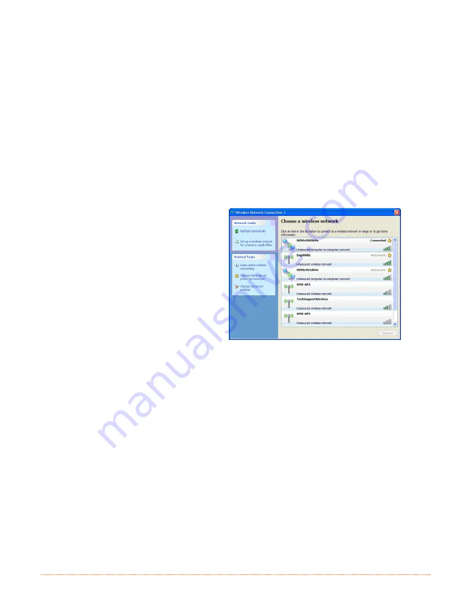
12. From Windows, you may now “View 

Wireless Networks”.   From the list of 

available wireless networks select the 

printer that you wish to connect to and 

then click on the Connect button.  


If you do not see your printer listed be 

sure you have the host computer 

configured for Ad-hoc wireless networks. 

This process will vary depending on your wireless device installed in your 
host computer and your operating system version.


Once the previous steps have been successfully completed you may now use the IP Address assigned to the 

printer to install a printer driver, and start printing from your Windows

®

 applications. See section B.3, 

Installing the Printer Driver.


Summary of Contents for E-Class Mark III Professional+

Page 1: ...Operator s Manual Professional and Professional Models Professional Professional ...

Page 2: ......

Page 3: ... party to duplicate or copy the Firmware or the information contained in the non volatile or programmable memory The firmware Software is protected by applicable copyright laws and Licensor retains all rights not expressly granted In no event will Licensor or its suppliers be liable for any damages or loss including direct incidental economic special or consequential damages arising out of the use...

Page 4: ...is equipment has been tested and found to comply with the limits for a Class A digital device pursuant to Part 15 of the FCC Rules These limits are designed to provide reasonable protection against harmful interference when the equipment is operated in a commercial environment This equipment generates uses and can radiate radio frequency energy and if not installed and used in accordance with the ...

Page 5: ...l Media 11 2 3 3 Loading Media with the Peel and Present Option 13 2 3 4 Loading Media with the Cutter Option 14 2 3 5 Adjustable Media Core Hangers Pro models only 15 2 4 Loading Ribbon 16 2 4 1 Using the Ribbon Core Adapters 19 3 3 3 P P Pr r ri i in n nt t te e er r r O O Op p pe e er r ra a at t ti i io o on n n 2 2 21 1 1 3 1 Introduction 21 3 2 LED Indicators 21 3 3 User Interface 22 3 3 1 F...

Page 6: ...e es s sh h ho o oo o ot t ti i in n ng g g 6 6 63 3 3 6 1 Introduction 63 6 2 Troubleshooting Tips 63 6 3 Hex Dump Mode 65 A A A S S Sp p pe e ec c ci i if f fi i ic c ca a at t ti i io o on n ns s s 6 6 67 7 7 B B B W W Wi i ir r re e el l le e es s ss s s a a an n nd d d W W Wi i ir r re e ed d d L L LA A AN N N S S Se e et t tu u up p p 7 7 71 1 1 B 1 Network Card Setup 71 B 2 Wireless Setup 7...

Page 7: ...www datamax oneil com If you wish to write custom programs or label formats a copy of the Programmer s Manual also is included for your reference or the manual can be downloaded 1 1 1 2 2 2 U U Un n np p pa a ac c ck k ki i in n ng g g t t th h he e e P P Pr r ri i in n nt t te e er r r After removing the printer from the packaging material check the contents of the box In addition to the printer ...

Page 8: ...ington slot allows you to physically secure the printer from being stolen by tethering it to a larger object like a desk or counter There are many security solutions offered by Kensington that are compatible with the slot Visit http www kensington com for a full line of locking options and accessories The Kensington Security Slot has been the industry standard since 1990 giving customers the best ...

Page 9: ... 2 1 Power Connections The printer is powered by an external auto ranging power supply which connects between the printer and an electrical outlet Ensure that the operating ranges of the power supply are compatible with your electrical service see Appendix A for details then connect power as follows Before connecting power to the printer ensure that the Power Switch is in the OFF O position 1 Conn...

Page 10: ...DB 9 connector with specific pin outs interface cable part numbers and pin outs are given below contact your reseller to order Serial port settings are menu selectable and must match the host settings Part 32 2483 01 Part 32 2301 01 The USB Port supports high speed serial communications and requires a standard USB interface cable The USB Host Port optional The USB Host Port allows the printer to a...

Page 11: ...ver Installation 1 Turn on the printer and wait until the start up initialization is complete The PC will then detect the printer and launch the Found New Hardware Wizard 2 Select the No not this time radio button and then click Next 3 Select the Install from a list or specific Advanced radio button and then click Next 4 Select the Search for the best driver in these locations radio button 5 Check...

Page 12: ...n the necessary ports to the printer 10 Click Finish to close the wizard Proceed to Step B to begin the installation of the Windows Printer Driver Step B Windows Printer Driver Installation 1 The PC will launch the Found New Hardware Wizard again 2 Select the No not this time radio button and then click Next ...

Page 13: ...n 5 Check the Include this location in the search checkbox and then click Browse 6 Navigate to driver folder on the CD ROM assuming your CD DVD drive is labeled D the path would be as follows My Computer D assets windriver 7 Select the folder and then Click OK Then Click Next 8 Select the driver that matches your model printer there may be multiple models listed and then click Next ...

Page 14: ...mpted click Continue Anyway 10 Windows will now install the necessary files for the Windows printer driver 11 Click Finish to close the wizard The printer can now be selected for use in the printer dialogue box of any windows application ...

Page 15: ...ll forward on the Cover Latches and lift up on the cover Pro models have Key Lock option that must be unlocked before the cover can be opened 312 Cover Latches Key Lock Option Pro models only 2 Slide the Media Guides outward Pro model Media Guides are equipped with Adjustable Media Core Hangers see section 2 3 5 3 Slide the Media Hangers outward and insert the Roll Media as shown Allow the Media H...

Page 16: ...rwise close the printer s Cover and press downward until latched Pro Pro models are equipped with a Cover Release Latch Press outward on the latch to release cover 312 Cover Cover Release Latch Pro models only 6 Press the button to advance the media if the Fault Light is lit see Section 3 7 The printer is factory set to use gap media If using another media type for example continuous media printer...

Page 17: ... Slide the Media Guides outward 2 Slide the Media Hangers outward and install the two Media Chute Guides into the Media Hangers Media Chute Guides Media Hangers External Media Guide 3 Position the Media Hangers to match the width of the media being used Slide the Hanger Lock against the Media Hanger to hold this position Media Hangers Hanger Lock ...

Page 18: ...External Media Slot Media Guides External Media Supply 5 If using Thermal Transfer media ribbon proceed to Section 2 4 Loading Ribbon Otherwise close the printer s Cover and press downward until latched 6 Press the button to advance the media if the Fault Light is lit see Section 3 7 The printer is factory set to use gap media If using another media type for example continuous media printer setup ...

Page 19: ...d then behind the Peel Roller and Peeler Door as shown below 312 Media Backing Peeler Door Platen Roller Peel Bar Peel Roller 4 Close the Peeler Door 5 If using Thermal Transfer media ribbon proceed to Section 2 4 Loading Ribbon Otherwise close the printer s Cover and press downward until latched 6 Press the button to advance the media if the Fault Light is lit see Section 3 7 7 The printer will n...

Page 20: ...and press downward until latched 4 Press the button to advance the media if the Fault Light is lit see Section 3 7 The printer will now cut each label as it exits from the printer 7 The printer will now peel each label and present it to the operator for removal If the printer is equipped with the Present Sensor Option the indicator light will flash orange and the next label will not feed print unt...

Page 21: ...w for support of media rolls with 3 1 5 or 1 cores To adjust 1 Pull outward in on the Core Hanger and slide the Core Hanger up or down to the desired setting Be sure both core hangers are set to the same position 312 Media Hanger Core Hanger 3 1 5 and 1 Core Positions Not in use Position for fanfold or external supply ...

Page 22: ...Ribbon Core Adapters see section 2 4 1 Ribbon Core Width 1 0 4 3 inches 25 110mm Centered on Ribbon Core Adapters Ribbon Width 1 0 4 3 inches 25 110mm Centered on core Load ribbon as follows If equipped with the thermal transfer option the printer is factory set to use ribbon see Section 3 4 to change this setting if using direct thermal media 1 Determine the type of ribbon C S I or C S O you are ...

Page 23: ...a Bouncer may need to be pushed out of the way 3 Once the Supply Roll is loaded slide the Ribbon Handler Latch downward to unlatch the Ribbon Handler Assembly 312 Supply Roll Supply Hub Media Bouncer Ribbon Handler Latch Ribbon Handler Assembly 4 Push out the Take up Hub and load an empty Ribbon Core into the printer as shown 312 Ribbon Core Take up Hub ...

Page 24: ...he leader of the ribbon to the Ribbon Core using Tape Rotate the Take up Hub Wheel several times to secure the ribbon 312 Ribbon Core Tape Take up Hub Wheel 7 Raise and latch the Ribbon Handler Assembly Close the cover and press the button to advance the media if the Fault Light is lit see Section 3 7 312 Ribbon Handler Assembly Cover ...

Page 25: ...he leader positioned as shown above onto a Core Adapter Slide an empty Ribbon Core onto the remaining Core Adapter 312 Core Adapter Ribbon Roll Ribbon Core 2 If using a narrow ribbon position the Ribbon Roll so that it is centered on the Core Adapter The Core Adapters are marked in both inches and centimeters to aid in proper positioning 312 Core Adapter Ribbon Roll ...

Page 26: ...20 Chapter 2 Printer Setup ...

Page 27: ...tus LED Red Error LED Graphic Display Directional Arrow Buttons Multi function Button 3 3 3 2 2 2 L L LE E ED D D I I In n nd d di i ic c ca a at t to o or r rs s s Two LED indicator lights provide a quick visual reference of printer operations and conditions as defined below LED 1 LED 2 Color Green Orange Red Solid Ready to print Paused or Present Sensor is blocked TOF sensing error Next TOF not ...

Page 28: ...nt job prompts user to resume or cancel Scrolls upward to the next menu item Scrolls downward to the next menu item N A N A 3 3 2 Test Mode The Test Mode contains test and informational label selections Print Quality Label Print Configuration Ribbon Test Label Test Label Validation Label Print Last Label Network Report Internally generated these labels are printed at pre selected media type speed ...

Page 29: ...ements the Count value Exits the Test menu mode Displays the Count screen 3 3 3 Menu Mode The menu mode is covered in detail in Chapter 4 Enters the Menu mode menu sub menu items Enter Accepts current prompt Scrolls upward to the next menu item Increments the current value Scrolls downward to the next menu item Decrements the current value Exits to the previous menus level Enters the next menu sub...

Page 30: ...s are simple HTML pages that can be accessed with any web browser via the optional Ethernet port Easy to use Printer can be configured from any host connected to the network regardless of physical location or host operating system No additional software required Printer must be equipped with an Ethernet or Wi FI option Depending on the complexity of the network initial connection may not be possib...

Page 31: ...cessories CD ROM that is included with your printer Older versions might not operate correctly with some printers For the latest version please visit our web site at http www datamax oneil com 1 Once installed launch the NETira CT configuration utility 2 Be sure the printer is ON Connect the host to the printer see Section 2 2 2 Interface Connections For Serial Connections a Query the printer by u...

Page 32: ...ay browse the Printer Component categories and make any changes necessary to the printer configuration 4 Once complete send the new settings to the printer using the Send button Note When sending the changes to the printer only the changes displayed on the current page will be sent You must click the Send button for each page that has been modified ...

Page 33: ... at http www datamax oneil com Installing the Windows Driver 1 Place the Accessories CD ROM included with your printer into your computers CD ROM drive 2 Once the CD ROM starts select your printer model then Install Driver from the menu and follow the instructions on the screen to install 3 When prompted select your printer from the list i e Datamax O Neil E 4xxx Mark III Continue to follow the on...

Page 34: ...tock setting matches the size of the label you are using If you cannot find a match for your label click New and enter the dimensions of your label Options Tab Print Speed Printhead Temperature These two settings will have the greatest effect on print quality Some label stocks will require more heat and slower print speeds to generate a quality image The Windows application software used to create...

Page 35: ...to access SENSOR CALIBRATION Make sure QUICK CALIBRATION is highlighted and press the button Using the button scroll to YES and then press the button to proceed Quick Calibration No Yes Select NO to abort this procedure D With the media installed and the cover closed press and hold the button until at least 2 full labels have been fed from the printer and then release Press Hold Enter Key There ar...

Page 36: ... is highlighted and press the button Using the button scroll to YES and then press the button to proceed Manual Calibration No Yes Select NO to abort this procedure D With no media installed and the cover closed press the button Remove Label Stock Press Enter Yyy This sets the empty value where yyy represents the current sensor reading E Load the media Be sure the Media Sensor is positioned correc...

Page 37: ...ete B Using the button scroll to MENU and press the button Make sure MEDIA SETTINGS is highlighted and press the button Then using the button scroll to SENSOR CALIBRATION Printer Menu C Press the button to access SENSOR CALIBRATION Make sure ADVANCED ENTRY is highlighted and press the button ADVANCED ENTRY D Scroll to TRAN SENSOR GAIN or REFL SENSOR GAIN if using reflective media then press the bu...

Page 38: ...NSOR GAIN 253 0 0 31 This is the Label Value for a gain setting of 0 Sample Calibration Table Gain Number Label Value TOF Value Difference Value 00 253 01 02 31 Step Action Displayed Message Comment G Using the button increment the Gain Number by one and then Record the Label Value Repeat this process for each Gain Number TRAN SENSOR GAIN 250 1 0 31 This is the Label Value for a gain setting of 1 ...

Page 39: ...SOR GAIN 09 31 0 31 1 Do not position the Media Sensor under a perforation and if using preprinted media ensure the label area placed over the sensor is free of text graphics lines etc 2 Do not move the Media Sensor after this step I Lower and latch the Cover Assembly Using the or button set the Gain Number to 0 Record the reading as a TOF Value for Gain Number 0 in the table TRAN SENSOR GAIN 248 ...

Page 40: ...essage Comment K In your sample calibration table where both the Label Value and TOF Value are at least 20 subtract the amounts and record the result as a Difference Value see below Identify the largest Difference Value and the corresponding Gain Number This Gain Number will be used to resample the media TRAN SENSOR GAIN 14 31 0 31 In the example below Gain Number 18 is chosen because both values ...

Page 41: ...bel over the Media Sensor then lower and latch the Cover Assembly Record the sensor reading as Paper B Raise the Cover Assembly Place the liner notch or mark over the Media Sensor then lower and latch the Cover Assembly Record the sensor reading as Gap or Mark C Raise the Cover Assembly Remove all media from the Media Sensor then lower and latch the Cover Assembly Record the sensor reading as Empt...

Page 42: ...ined in Step M and then press the button GAP SENSOR LEVEL 042 0 255 This is the Gap or Mark value P Using the button scroll to EMPTY SENSOR LEVEL and then press the button Set the Empty value determined in Step M and then press the button EMPTY SENSOR LEVEL 9 0 255 This is the Empty value Q Press the repeatedly to exit the menu select YES at the SAVE CHANGES prompt and then press the button Save C...

Page 43: ... Menu accesses all operational settings functions and diagnostics Prompts may appear before menu access is granted and before changes are enacted see Security for details 4 4 4 2 2 2 T T Th h he e e U U Us s se e er r r M M Me e en n nu u u The User Menu contains basic selections in these menus Media Settings Print Control Printer Options System Settings 1 Some setting changes will only become eff...

Page 44: ...o scroll to MENU and then press the button 2 Using the button scroll to SYSTEM SETTINGS then press the button 3 Be sure the cursor is next to MENU MODE then press the button 4 Using the button scroll to ADVANCED MENU then press the button Upon completion OK will be displayed and the printer will exit the menu system 1 Some setting changes will only become effective and saved after selecting YES at...

Page 45: ...recognized by sensing the holes in the field of the media BLACK MARK TOF will be recognized by sensing the reflective black marks on the underside of the media CONTINUOUS No TOF sensing will be used instead LABEL LENGTH in Media Settings is used AUTO CALIBRATION The printer will sense each label as it exits the printer and continually make sensor adjustments to ensure the best possible calibration...

Page 46: ...NSOR LEVEL Establishes the threshold for the paper value 0 255 where 170 is the default setting REFL PAPER LEVEL Establishes the threshold for the reflective value 0 255 where 170 is the default setting GAP SENSOR LEVEL Establishes the threshold for the gap value 0 255 where 040 is the default setting MARK SENSOR LEVEL Establishes the threshold for the mark value 0 255 where 040 is the default set...

Page 47: ...stop position 0 4 00 inches past the start of print position upon output When subsequent label formats are received the printer will automatically back up the label to position it at the start of print position where 0 00 in Is the default setting When set to 0 01 in NONE is assumed and a zero 0 positioning value will be used TOF PRECEDENCE Allows an override of label format data when the form len...

Page 48: ...available for formatting by the printer Choosing FORMAT MODULE will erase existing data in the selected module DELETE FILE Selects from the list of available files for deleting COPY FILE Selects from the list of available files for copying prompting you for the destination module before execution UNPROTECT MODULE Selects from the list of available modules to unprotect and then prompting you regard...

Page 49: ...re USER MENU Accesses limited basic menu items ADVANCED MENU Accesses all menu items CONFIGURATION FILE Controls the creation storage and recall of printer configuration files where RESTORE AS CURRENT Returns the printer to a previously saved configuration SAVE SETTING AS Creates a file based on the current printer configuration as described here DELETE FILE Removes a selected configuration file f...

Page 50: ...1004 WINDOWS GREEK 8 PC 775 BALTIC WINDOWS 3 0 LATIN 1 PC 8 GREEK PTXT3000 WINDOWS LATIN CYRIC ISO 21 GERMAN NON UGL PI FONT WINDOWS 3 0 LATIN 5 HEBREW 7 ROMAN 8 HEBREW 8 ROMAN 9 Reference the Programmer s Manual for code page symbol set details DOUBLE BYTE SYMBOLS Selects the optional ILPC code page used to print double byte fonts where JIS Japanese Industry Standard SHIFT JIS Shift Japanese Indu...

Page 51: ... LABEL ROTATION Allows the label format to be rotated 180 degrees before printing where ENABLED Flips the format DISABLED Does not flip the format Default Setting IMAGING MODE Determines the process used to format labels where MULTIPLE LABEL Images multiple labels as memory permits to achieve the fastest throughput If time stamping labels however the indicated time will reflect the moment of imagi...

Page 52: ...RO Processes DPL data as an Allegro including row position calculations based on 194 dots per inch and the exceptions noted below PRODIGY PLUS Processes DPL data as a Prodigy Plus including column calculations based on 200 dots per inch and the exceptions noted below PRODIGY Processes DPL data as a Prodigy including column calculations based on 200 dots per inch and the exceptions noted below Exce...

Page 53: ...er state i e heat speed settings etc and the label formatting commands for the stored label Default Setting FIELDS ONLY Recalls the label formatting commands for the stored label MENU LANGUAGE Selects the menu and configuration label language Only languages that are resident will be displayed see Appendix D where ENGLISH Enables English Default Setting DISPLAY SETTINGS Determines the appearance of...

Page 54: ...ere NONE Parity is not used Default Setting ODD Odd parity is used EVEN Even parity is used DATA BITS Sets word length where 7 8 8 A seven or eight bit word is selectable and is the Default Setting STOP BITS Sets the number of stop bits where 1 2 1 One stop or two stop bits are selectable and is the Default Setting PARALLEL PORT A Controls the communication setting for the parallel port where PORT...

Page 55: ...pecified static value will be used Default Setting A server assigned IP address takes precedence over any static IP address stored in the interface STATIC IP ADDRESS Specifies the static IP Address of the interface in the standard octet format STATIC SUBNET MASK Specifies the static Subnet assigned to the interface for example 255 255 255 000 STATIC GATEWAY Specifies the Gateway Address the interf...

Page 56: ...ontrols the communications settings for the Bluetooth network interface where DISCOVERABLE Yes No Determines whether other Bluetooth devices in range can detect the printer CONNECTABLE Yes No Determines whether other Bluetooth devices in range can connect to the printer BONDABLE Yes No Determines whether other Bluetooth devices in range can create a bondable connection with the printer AUTHENTICAT...

Page 57: ...HEAT COMMAND Determines the way the DPL Heat command is handled where ENABLED Processes commands normally Default Setting DISABLED Ignores DPL Heat commands instead the heat value is controlled via the menu setting SPEED COMMANDS Determines the way DPL Print Feed Slew and Reverse commands are handled where ENABLED Processes commands normally Default Setting DISABLED Ignores DPL speed commands inst...

Page 58: ...g LABEL PRESENTED when a label blocks the sensor and LABEL NOT PRESENTED when no label blocks the sensor Note that this test can also be used to check the sensor function of the Peel Present option TEST CUTTER Performs a functional test of the Cutter where PERFORM TEST 001 TIMES Cycles the cutter blade a selected number of times 0 999 with PASS FAIL results given for each cycling attempt PRINT TES...

Page 59: ... cotton swab to clean the printhead from end to end After every roll of media Platen Roller Turn OFF the printer Rotate the platen roller and clean it thoroughly with solvent applied with a cotton swab After every roll of media Peel Off Roller Rotate the peel off roller and clean it thoroughly with solvent applied with a cotton swab After every roll of media Media Path Solvent After every roll of ...

Page 60: ...eaning methods are recommended Streaks can indicate a dirty or a faulty printhead Proper cleaning is critical To maintain peak performance of the printer Datamax O Neil offers a complete line of cleaning products including pens cards films and swabs To learn more visit our website Cotton Swab Procedure If printing with direct thermal media or thermal transfer media with wax ribbon clean the printh...

Page 61: ...is completes cleaning Cleaning Film Procedure If printing with thermal transfer media and resin ribbon when printing with a Heat Value of 22 or higher or when other methods prove unsuccessful clean the printhead as follows 1 Open the printer Wait briefly for the Printhead to cool 2 Remove media and ribbon then place a sheet of Cleaning Film under the Printhead part number 70 2087 01 3 Close the co...

Page 62: ... printers equipped with the thermal transfer option allows the optimum amount tension to be supplied by the ribbon supply hub Adjust the ribbon tension as follows 1 Turn off the printer 2 Hold the ribbon ribbon hub to prevent it from turning Then push in and rotate the Ribbon Tension Adjustment Knob to the position that matches the core size of the ribbon in use 312 Ribbon Handler Ribbon Tension A...

Page 63: ... path where the gap between the labels crosses the sensors top and bottom sensors must be aligned Separate Die Cut and Notched Use this for the Notched or Hole Media Notched Hole Center of the Notch or Hole Gap primary Reflective secondary Black Bar Center of the Black Mark Reflective Position the AMS as follows 1 On the Bottom AMS Sensor identify the proper Indicator for use with your media Gap o...

Page 64: ...w proper Electro Static Discharge procedures when replacing the printhead 1 Turn OFF the printer and remove the ribbon if installed 2 Lower the Ribbon Handler Assembly 3 Press outward on the two Printhead Carrier Tabs and rotate the Printhead Carrier down 312 Ribbon Handler Printhead Assembly Tabs Printhead Carrier 4 Press inward on the two Printhead Shield Tabs and rotate the Printhead Shield dow...

Page 65: ...head Screw Printhead Printhead Cable Sensor Installation 1 Carefully connect the Printhead Cable to the new Printhead 2 Position the Printhead in the Printhead Carrier and tighten the Printhead Screw 3 Ensure the Sensor properly seated and rotate the Printhead Shield upward until it snaps into place 4 Rotate the Printhead Carrier upward until it snaps into place ...

Page 66: ...ly removed for cleaning replacement or clearing media jams 1 Turn OFF the printer and remove the media if installed 2 Lift up on the two Platen Roller Tabs 312 Platen Roller Tabs 3 Remove the Platen Roller Assembly from the printer 312 Platen Roller Assembly Installation 1 Position the Platen Roller Assembly into the printer 2 Rotate the two Platen Roller Tabs downward until they snap into place ...

Page 67: ...elect the binary file BIN file 4 Click the Send button to start the firmware update 5 7 1 Boot 1 and Boot 2 Boot Loaders 1 Connect the printer to your PC using a serial cable 2 Launch the NETira CT configuration utility and query connect to the printer see section 3 5 for more information on NETira CT It is recommended that the configuration be saved before downloading firmware and restored when f...

Page 68: ...62 Chapter 5 Maintenance Adjustments ...

Page 69: ...the media being used Use the software program or DPL commands adjust the Heat Setting and Print Speed A mismatched incorrect ribbon media combination is being used Check the types being used Faulty printhead Replace it see Section 5 5 or call for service The printer does not print or prints several labels at once The labels are incorrectly loaded See the loading instructions on the inside cover of...

Page 70: ...efore a fault indication The ribbon may be incorrectly installed Ensure that the inked side of the ribbon faces the labels With most ribbons this can be verified by rubbing paper against the ribbon the ink should smudge the paper Or if using label stock the sticky side of a label will pull off the ink A mismatched ribbon paper combination is resulting in an insufficient amount of friction between ...

Page 71: ...s of missing data in the character string To print the Hex Dump Label To begin go to the Diagnostics menu and enable Hex Dump Mode see Section 4 4 Exit the menu and save the changes Now HEX DUMP MODE will be indicated by the display and all data sent to the printer will now be output in hexadecimal code along with the printable ASCII equivalents as shown below To exit Hex Dump Mode re enter the Di...

Page 72: ...66 Chapter 6 Troubleshooting ...

Page 73: ...18 7 cm Pro Models 9 45 inches 24 0 cm Weight Pro Models 5 25 pounds 2 4 kg Pro Models 7 75 pounds 3 5 kg Operating Temperature 40 to 95 F 4 to 35 C AC Input Voltage Power Supply 105 VAC to 250 VAC 50 60 Hz Printing Print Method Direct Thermal Thermal Transfer optional Print Speed 203 DPI Models 2 6 IPS 50 8 152 4mm s 300 DPI Models 2 5 IPS 50 8 127mm s Resolution 203 DPI Models 203 DPI 8 dots mm ...

Page 74: ...res Ribbon Width Range Core Ribbons Ribbon Core Width 4 3 inches 110mm Ribbon Width 1 0 4 3 inches 25 110mm Centered on core 1 Core Ribbons with Ribbon Core Adapters see section 2 4 1 Ribbon Core Width 1 0 4 3 inches 25 110mm Centered on Ribbon Core Adapters Ribbon Width 1 0 4 3 inches 25 110mm Centered on core Ribbon Roll Capacity 0 5 13mm core with 361 110m long ribbon or 1 25mm core with 984 30...

Page 75: ...the center of the media to the center of media sensor aperture The distances differ for right of center and left of center and are dependant on whether transmissive or reflective media is being used Transmissive Gap Hole Notch 42mm to left and 34mm to right Reflective Bar Hole Notch 58mm to left and 38mm to right H Reflective mark width 2 4 4 50 I Distance between reflective marks 24 3 25 5 J Refl...

Page 76: ...70 Appendix A Specifications ...

Page 77: ...important default information such as the IP and MAC Addresses as well as SSID for wireless equipped cards To print the Network Report Press the button to highlight the TEST menu branch and then press the button Using the button scroll to Network Report and then press the button When prompted choose either View to view the information on the display or Print to print the information 4 Verify the p...

Page 78: ...l appear The printer s internal web pages are divided into 10 pages that are accessible via the navigation bar on the left hand side Most of the items on these pages mimic the printer s internal menu For more information on the function of these settings see the corresponding function in Chapter 4 You must provide a password to change any settings the default password is sysadm If any address para...

Page 79: ...ection enter valid static IP addresses for Printer IP Address Printer Subnet Mask and Printer Gateway 3 Scroll down the page to Network Type select infrastructure from the drop down box 4 In the SSID field type the name of the SSID of your access point 5 Under the WIFI Security and Authentication set any security authentication settings necessary for your network 6 Scroll down to the bottom of the...

Page 80: ...Wireless Setup Ad Hoc After a successful setup is made via a wired connection the Wireless connection if equipped can now be configured in ad hoc mode using a static IP address To configure the wireless card in Ad hoc mode you must configure your host computer to match the IP settings of the printer Refer to your operating system s or your wireless network card documentation for information on how...

Page 81: ...own box Enter the password at the top of the page default is sysadm and click Execute to restart the printer 11 The printer will now search for a server Allow up to 90 seconds for the printer to retrieve an IP address 12 From Windows you may now View Wireless Networks From the list of available wireless networks select the printer that you wish to connect to and then click on the Connect button If...

Page 82: ...s Add Printer Wizard The following screen should appear and then click Next 2 Make sure that Local Printer is selected and then click Next 3 Select Create a new port and then select Standard TCP IP Port from the drop down menu Click Next 4 Click Next 5 In the Printer Name or IP Address field enter the IP address of your printer The Port Name field does not need to be changed When finished click Ne...

Page 83: ...and select whether or not it is to be your default printer then click Next 14 Select whether or not to share this printer on your network Then click Next 15 Select No then Click Next 16 Confirm your settings and then click Finish 17 If prompted with the Digital Signature Not Found window click Yes to continue installation 18 Your computer will now copy the necessary files from the CD ROM The drive...

Page 84: ...78 Appendix B WLAN LAN Setup ...

Page 85: ...ection of the configuration utility 2 In the Primary Interface setting from the drop down box select Bluetooth Send the new setting to the printer using the Send button Allow 30 seconds for the printer to reset 3 Click the Bluetooth menu under the Printer Component section of the configuration utility 4 To set up the printer for Bluetooth change or confirm the following parameter settings Bondable...

Page 86: ...80 Appendix C Bluetooth Setup ...

Page 87: ...ge column or modify the existing column in the spreadsheet click on the Generate DPL file s radio button and then send that file s to the printer Software requirements for modifying the menu language are as follows Microsoft Excel must be purchased by user Img2dl exe provided at ftp ftp datamax oneil com Printer 20Firmware EFIGS A I M W Class is a program used during the process to create the DPL ...

Page 88: ...n trying to modify the MAX value however if cutting and pasting fields this warning system may be defeated Two Line Messages Some of the message are displayed as two lines These are indicated in the comment fields Comments This field can be modified with no effect D After editing is complete highlight all of the columns to be created by pressing the letter above the column more than one column can...

Page 89: ...guage Save the changes when prompted A reset will occur as font validation is performed An error has occurred if the printer displays the new language selection but all messages remain in English In this case re check your process or contact Datamax O Neil Technical Support be ready to provide the Common xls and DPL download files created Other error messages are also possible Menu Language Error ...

Page 90: ...troying the new menu language s Module Y can be UNLOCKED by sending this DPL string STX KpY0 To restore the factory generated EFIGS image download the file 832296 01A to the printer This file is located on the Datamax O Neil FTP site The letter at the end of the file name e g A specifies the revision The latest revision will be available on the FTP site Downloading the same language twice will aut...

Page 91: ...Appendix D Menu Language 85 The screen shot below is an example of Unicode defined languages Chinese Russian Note the only additional information required is the double in row 1 ...

Page 92: ......

Reviews: