COMPONENT SPECIFICATION
C00525
C00525
C00525
C00525
- 13 -
APPENDIX 4 – TEST FOR LATCH INTEGRITY
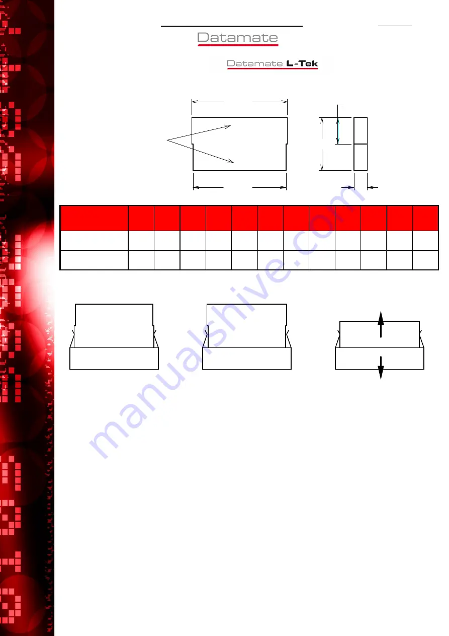
A4.1. LATCH INTEGRITY GAUGE
B
A
20
10
5
Dim ‘B’
Dim ‘A’
Remove all burrs
and sharp edges
‘A’ and ‘B’ stamped
in positions shown
No. of contacts
No. of contacts
No. of contacts
No. of contacts
per row
per row
per row
per row
2222
3333
4444
5555
6666
7777
8888
9999
10
10
10
10
13
13
13
13
17
17
17
17
22
22
22
22
Dim ‘A’
+0.00 / -0.02
6.00
8.00
10.00 12.00 14.00 16.00 18.00 20.00 22.00 28.00 36.00 46.00
Dim ‘B’
+0.02 / -0.00
5.00
7.00
9.00
11.00 13.00 15.00 17.00 19.00 21.00 27.00 35.00 45.00
A4.2. LATCH INTEGRITY TEST
B
A
B
A
Figure 1
Figure 2
Figure 3
When Gauge A is placed between the two faces of the latch clips (as shown in Figure 1), the connector
shall be held against its own weight.
When Gauge B is placed between the two faces of the latch clips (as shown in Figure 2), the connector
shall not be held against its own weight.
When an unloaded female connector moulding is mated with a latched male connector, and a force of
20N is applied for 10 seconds in the directions shown in Figure 3, there shall be no failure of any part
of the latch mechanism.


