background image

Dispenser Design Guidelines

4

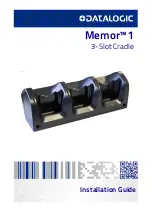
Memor™ 1 3-Slot Cradle

Summary of Contents for Memor 1

Page 1: ...Memor 1 3 Slot Cradle Installation Guide...

Page 2: ...eproductions of the documentation Should future revisions of this manual be published you can acquire printed versions by contacting your Datalogic representative Electronic versions may either be dow...

Page 3: ...nfiguration J8 15 Configuration J9 16 Configuration J10 17 Configuration J11 18 Base Unit Configurations Summarizing Table 18 Ventilation Grilles Position 20 Shopper Unit Placing and Unity Definition...

Page 4: ...ii Memor 1 3 Slot Cradle Powering the Cradle 41 LED Indicators 45 Radio Technologies and Frequency Bands 47 Technical Specifications 48 Maintenance 50 Cleaning 50 Safety Precautions 51 Cabinet 51...

Page 5: ...different kinds of retail environments The layout indications are suggestions to help design a functional cabinet The second part of the document gives some technical details needed to build a vertica...

Page 6: ...Introduction 2 Memor 1 3 Slot Cradle NOTES...

Page 7: ...he most profitable way to place the devices following their height from the floor The devices placed in the higher part of the dispenser between 1m and 1 60m perform their communicative function in th...

Page 8: ...Dispenser Design Guidelines 4 Memor 1 3 Slot Cradle...

Page 9: ...ts some may need a tall base but not deep or large some may need a short base but can accept larger and bulkier sizes There are basically two different solutions organizing the disposition of the devi...

Page 10: ...1 3 Slot Cradle NOTE To guarantee full stability the cabinet must be anchored to the wall or to the floor see Anchoring and Maintenance Issues on page 38 The front door dispenser must have a jamb of 2...

Page 11: ...Dispenser Design Guidelines Installation Guide 7 Configuration J0 Back Door Dispenser High Density Hand Held...

Page 12: ...Dispenser Design Guidelines 8 Memor 1 3 Slot Cradle Configuration J1 Front Door Dispenser High Density Hand Held...

Page 13: ...Dispenser Design Guidelines Installation Guide 9 Configuration J2 Back Door Dispenser High Density Pistol Grip...

Page 14: ...Dispenser Design Guidelines 10 Memor 1 3 Slot Cradle Configuration J3 Front Door Dispenser High Density Pistol Grip...

Page 15: ...Dispenser Design Guidelines Installation Guide 11 Configuration J4 Back Door Dispenser High Visibility Hand Held...

Page 16: ...Dispenser Design Guidelines 12 Memor 1 3 Slot Cradle Configuration J5 Front Door Dispenser High Visibility Hand Held...

Page 17: ...Dispenser Design Guidelines Installation Guide 13 Configuration J6 Back Door Dispenser High Visibility Pistol Grip...

Page 18: ...Dispenser Design Guidelines 14 Memor 1 3 Slot Cradle Configuration J7 Front Door Dispenser High Visibility Pistol Grip...

Page 19: ...Dispenser Design Guidelines Installation Guide 15 Configuration J8 Back Door Inclined Dispenser High Visibility Hand Held...

Page 20: ...Dispenser Design Guidelines 16 Memor 1 3 Slot Cradle Configuration J9 Back Door Inclined Dispenser High Visibility Pistol Grip...

Page 21: ...Dispenser Design Guidelines Installation Guide 17 Configuration J10 Back Door Hybrid Dispenser Hand Held...

Page 22: ...gurations Summarizing Table Dispenser Configuration Vertical podsrowsn Tilted Pods rows n Dispenser height cm Dispenser depth cm Highest pod height cm Lowest pod height cm J0 0 11 180 50 170 49 J1 0 1...

Page 23: ...Dispenser depth cm Highest pod height cm Lowest pod height cm J7 0 6 180 20 160 40 J8 10 0 160 75 160 47 J9 6 0 160 75 156 47 J10 4 6 165 50 163 5 45 J11 3 6 165 50 165 40 NOTE The dimensions previous...

Page 24: ...Dispenser Design Guidelines 20 Memor 1 3 Slot Cradle Ventilation Grilles Position...

Page 25: ...where two or more shopper units share the same dispensing furniture a physical boundary must be placed to indicate the dispensing areas related to each Shopper Unit The purpose of this boundary is to...

Page 26: ...Dispenser Design Guidelines 22 Memor 1 3 Slot Cradle NOTES...

Page 27: ...s not a trivial job as it might seem In this section instructions are given to correctly build a Dispenser Base Unit The same instructions can be used to build Base Units containing a different number...

Page 28: ...abinet Use at least 12 screws to fasten each bracket The red circled spacer in the figure below is used to set the horizontal pitch in case the panel is not pre drilled Remove it from the last bracket...

Page 29: ...r supply cable through the proper hole the right hole is for high visibility configuration the left hole is for high density configuration Connect the cradle to the power supply see Powering the Cradl...

Page 30: ...Cradle 3 Place the cradle on the mounting bracket as shown in the pictures below Ensure there is no gap between the bracket and the cradle Fix the cradle to the bracket using the two screws included i...

Page 31: ...Dispenser Construction Details Installation Guide 27 High Density Configuration...

Page 32: ...he unlock key provided with the cradle or by software sending an unlock command from the inserted device see the Memor 1 user s manual or the SDK documentation To locally unlock the cradle and remove...

Page 33: ...nser Construction Details Installation Guide 29 Base Unit Construction Details Pattern Holes The following drawings show the suggested cabinet s pattern holes for each configuration High Density Hand...

Page 34: ...Dispenser Construction Details 30 Memor 1 3 Slot Cradle High Density Pistol Grip...

Page 35: ...Dispenser Construction Details Installation Guide 31 High Visibility Hand Held...

Page 36: ...Dispenser Construction Details 32 Memor 1 3 Slot Cradle High Visibility Pistol Grip...

Page 37: ...Dispenser Construction Details Installation Guide 33 Tilted Panel High Visibility Hand Held...

Page 38: ...Dispenser Construction Details 34 Memor 1 3 Slot Cradle Tilted Panel High Visibility Pistol Grip...

Page 39: ...Dispenser Construction Details Installation Guide 35 Hybrid Panel Hand Held...

Page 40: ...Dispenser Construction Details 36 Memor 1 3 Slot Cradle Hybrid Panel Pistol Grip...

Page 41: ...tion Details Installation Guide 37 Custom If you want to design your own custom configuration there is a minimum distance to respect to guarantee the unmounting of the cradles and removal of the Memor...

Page 42: ...must be firmly anchored to the floor Also the Shopper Unit or its exposed parts like monitor and scanners must be firmly anchored to the cabinet Protection Against Cart Trolley Impacts Carts and trol...

Page 43: ...can provide for a 12V 6A 72W Max DC output with constant voltage source Input Requirements AC input voltage Maximum voltage 264Vac Normal voltage 100 240Vac Minimum voltage 90Vac AC input frequency Ma...

Page 44: ...Output voltage and current Output voltage Vdc 12V 5 Current min A 0A Current max A 6A Voltage isolation The DC ground will be isolated from the AC neutral and AC line Environment Temperature Operatin...

Page 45: ...stallation Guide 41 Powering the Cradle Each power supply must be mounted on its bracket inside the cabinet as shown in the figure below There are two options to connect the cradle to the power supply...

Page 46: ...power supply into the AC DC plug using a Datalogic power cable Please see below an example of how to insert the power supply cable through the wall mounting metal bracket Standard Charge The standard...

Page 47: ...talogic power cable CAUTION Use only the Datalogic power supply 91ACC0048 to power the Memor 1 3 Slot Cradle NOTE Insert the device into the dock with the screen facing front and the head facing down...

Page 48: ...Dispenser Construction Details 44 Memor 1 3 Slot Cradle CAUTION Do not put any foreign object such as but not limited to coins paper clips stickers inside the slot of the dock see the example below...

Page 49: ...nlocked if programmed to use green led to notify unlock status or it could be controlled by software using our SDK Maintenance LED Red LED Blink red 1 quick pulse single slot Cradle not calibrated Usu...

Page 50: ...by the terminal for too much time Typically it is caused by a bug in the terminal firmware The power transfer is disabled Blink red 5 quick pulses single slot WLC generic error The WLC system seems un...

Page 51: ...logies and Frequency Bands Memor 1 3 Slot Cradle incorporates the following radio technologies and supports the corresponding frequencies as specified below Radio Technology Frequency Bands NFC Near F...

Page 52: ...a The Memor 1 should be charged at an ambient temperature between 0 35 C to achieve the maximum charging rate Never charge the main device in a closed space where excessive heat can build up Close to...

Page 53: ...High Visibility 313x183x134mm 12 32x7 20x5 28in Cradle High Density 313x113x113mm 12 32x4 45x4 45in Cradle with Memor 1 Handheld High Density 313x113x162 12 32x4 45x6 38in Cradle with Memor 1 Pistol G...

Page 54: ...adle using a soft cloth slightly dampened with only water or Isopropyl Alcohol 70 Do not use any other cleaning agents e g different alcohol abrasive or corrosive products solvents or abrasive pads to...

Page 55: ...he power supply must be adhered to in order to avoid overheating problems for the components inside the cabinet All components having dangerous voltage levels must be protected from unauthorized acces...

Page 56: ...ved Datalogic and the Datalogic logo are registered trademarks of Datalogic S p A in many countries including the U S and the E U Datalogic S r l Via S Vitalino 13 Lippo di Calderara di Reno BO 40012...

Reviews: