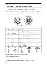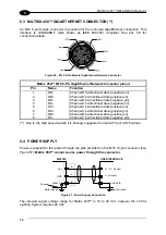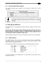
MATRIX 450™ ELECTRICAL CONNECTIONS
71
5
5.2 MATRIX 450™ LIGHTING SYSTEM CONTROL CONNECTOR
Matrix 450™ controls the LT-03x series lighting system from this connector through software.
Matrix 450™ can also receive power from this input, normally from the LT-03x lighting
system through the CAB-LD-002 cable.
Matrix 450™ cannot source power through this
connector
.
Figure 54 - M12 8-pin Male Lighting System Control Connector
Matrix 450™ M12 8-pin Lighting System Connector Pinout
Pin Name Function
1
SPOT1
Red Spot control signal
2
STROBE
Illuminator control signal
3
SPOT2
Green Spot control signal
4
AIMING
Aiming Lasers control signal
5
LDA
I2C channel data signal
6
LDL
I2C channel clock signal
7
GND
Power supply input voltage negative
8
VDC (*)
Power supply input voltage positive
(*) in the CAB-LD-102 LT Driver No Power cable, this pin isn’t connected. In this way the
Matrix 450™ is powered ONLY from pin A of the M16 19-pin male connector.
5.2.1 LT-03x Input Power Connector (on LT-03x)
The LT-03x lighting system must be powered from this connector.
PIN 4
PIN 3
PIN 1
PIN 2
Figure 55 - M12 4-pin Male LT-03x Input Power Connector
LT-03x M12 4-Pin Input Power Connector pinout
Pin Name Function
1
VDC
Power supply input voltage positive
2
VDC
Power supply input voltage positive
3
GND
Power supply input voltage negative
4
GND
Power supply input voltage negative
Summary of Contents for Matrix 450
Page 1: ...MATRIX 450 Reference Manual...
Page 12: ...xii...
Page 160: ...www automation datalogic com...


