


INTRODUCTION
32
MATRIX 320
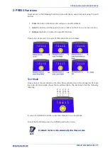
INDICATORS AND KEYPAD BUTTON
Figure 14 - Indicators
The following LED indicators are located on the reader:
PWR
blue LED indicates that the reader is connected to the power supply (Figure
14, 1)
NET
yellow LED indicates connection to the on-board Ethernet network (Figure
14, 2)
In normal operating mode the colors and meaning of the five LEDs are illustrated in the
following table:
STATUS
red LED indicates a NO READ result (Figure 14, 3)
COM
yellow LED indicates active communication on the main serial port
* (Figure 14, 4)
TRIGGER
yellow LED indicates the status of the reading phase (Figure 14,
5)
GOOD
green LED confirms successful reading (Figure 14, 6)
READY
green LED indicates that the reader is ready to operate (Figure
14, 7)
* When connected to a Fieldbus network through the CBX500, the COM LED is always active, even
in the absence of data transmission, because of polling activity on the Fieldbus network.
During the reader startup (reset or restart phase), these five LEDs blink for one second.
In X-PRESS Configuration mode the colors and meaning of these five LEDs are described
in X-PRESS Human Machine Interface.
The keypad button (Figure 14, 8) is software programmable. By default it starts the X-
PRESS interface for quick installation without using a PC (see "
Summary of Contents for Matrix 320
Page 1: ...Matrix 320 PRODUCT REFERENCE GUIDE Image Based Industrial Reader...
Page 88: ...CBX ELECTRICAL CONNECTIONS 74 MATRIX 320 Figure 54 NPN External Trigger Using Matrix 320 Power...
Page 133: ...Reader 2 Reader 3 PASS THROUGH CONFIGURATIONS PRODUCT REFERENCE GUIDE 119...
Page 141: ...INTERNAL NETWORK CONFIGURATIONS PRODUCT REFERENCE GUIDE 127...
Page 143: ...INTERNAL NETWORK CONFIGURATIONS PRODUCT REFERENCE GUIDE 129 Open the cloned application job...