


INTRODUCTION
1
1.3 MODEL DESCRIPTION
The DX8200A scanner is available in versions that differ depending on the interface
connection, the optical resolution and on the input power type:
DX8200A - 3 X Y Z
Power:
0 = VDC
Optical Resolution:
1 = Medium resolution
Communication Type:
0 = Standard version
1 = Ethernet version
2 = High resolution
3 = Very High resolution
1 = VAC
2 = Profibus version
3 = DeviceNet version
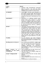
1.4 INDICATORS
The DX8200A has five LEDs on the rear panel.
The indicators have the following functions:
POWER ON
(green) Indicates the scanner is turned on.
PHASE ON*
(yellow) Indicates the external presence sensor is active.
ENCODER*
(yellow) Indicates the external encoder signal is active.
TX DATA
(green) Indicates data transmission both on the main and on the auxiliary
interface.
NETWORK
(red)
Indicates the Lonworks network is functioning correctly. This LED is
normally ON.
* These LEDs are always OFF when the DX8200A works as Slave.
3


