MECHANICAL INSTALLATION
43
3
3.2 MECHANICAL INSTALLATION
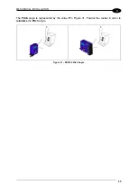
DS5100 can be installed to operate in different positions. The four screw holes (M4 x 5mm
depth) on the body of the reader are for mechanical fixture to the L-shaped mounting
bracket.
There are also three screw holes (M5 x 5mm depth) for fixture to the U-shaped mounting
bracket.
The following diagrams give the overall dimensions of the scanner and mounting brackets
and may be used for installation. Refer to par. 3.2.1 and 3.4 for correct positioning.
Figure 15
– DS5100 Standard Serial Model Overall Dimensions
mm
[in]
Summary of Contents for DS5100
Page 1: ......
Page 30: ...DS5100 REFERENCE MANUAL 14 1 b Digital Outputs configuration c Hardware interface selection...
Page 62: ...DS5100 REFERENCE MANUAL 46 3 Figure 18 DS5100 OM Serial Model Overall Dimensions...
Page 78: ...DS5100 REFERENCE MANUAL 62 4 Figure 38 ID NET Network Connections with isolated power blocks...
Page 97: ...TYPICAL LAYOUTS 81 5 7 Double click on the DS5100 scanner to configure it...
Page 163: ...147 X X PRESS Human Machine Interface 23...
Page 164: ......


