background image


DM-

SV01  ●  Product Manual  ●  Rev. 1.1 

36   


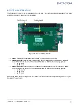
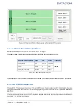
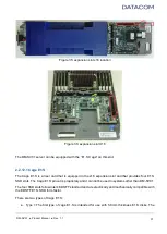
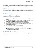
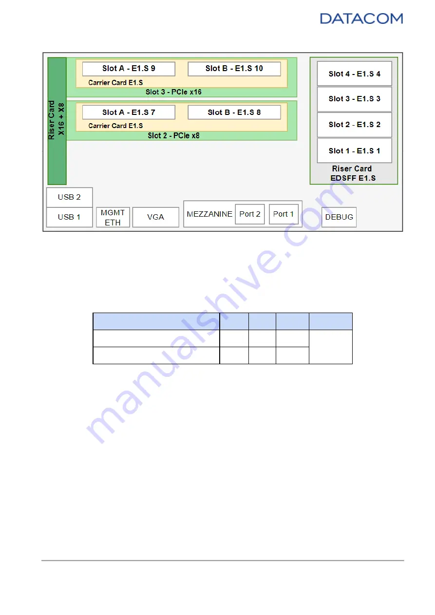
Figure 34: Risercard PCIe x16+x8 equipped with 2x E1.S PCIe Adapter Card 


2.2.11.3.1 2xE1.S Adapter Power Specifications 

Each E1.S slot can deliver up to 12W to the SSD. The table below shows the power specifications for 
each E1.S SSD slot of the 2xE1.S PCIe Adapter Card. 


2x E1.S PCIe Adapter Card slot  V(V) 

I(A) 

P(W) 

Total (W) 

Slot A 

12 

12 

24 

Slot B 

12 

12 

Table 16

: 2x E1.S PCIe Adapter Card - power specifications 


2.2.12 X16 Expansion Slot 

The DM-SV01 server has a proprietary connector with 16 PCIe lanes, used for connecting an expansion 
Riser Card. 


Summary of Contents for DM-SV01

Page 1: ...DM SV01 Server Product Manual Revision 1 1 Last updated Nov 2022 DATACOM...

Page 2: ...ty for any errors or omissions as well as no obligation is assumed for damage resulting from the use of the information contained in this manual In no event will Datacom or its suppliers be liable for...

Page 3: ...on POWER SW 14 2 2 1 2 Reset button RESET SW 15 2 2 1 3 Unit ID button ID 15 2 2 2 LEDs 16 2 2 2 1 Power Standby LED PWR STBY 17 2 2 2 2 Power Active LED PWR ACT 17 2 2 2 3 System Fail LED SYS FAIL 18...

Page 4: ...47 3 3 1 Inserting the DM SV01 server into the DM1904 47 3 3 2 Removing the DM SV01 server from the DM1904 47 4 Powering up the System Quick Start Guide 49 4 1 Powering up the DM SV01 49 4 2 Connecti...

Page 5: ...isaggregated systems 77 6 1 Storage solutions JBOD HBA card 77 6 2 JBOF PCIe retimer card cables 77 6 3 GPU units 78 7 References 79 8 Annex A DM SV01 Ecodesign Specifications 80 8 1 A 1 Low End Confi...

Page 6: ...are manufactured using 7nm process technology which provides outstanding results in terms of processing capacity and energy efficiency The DM SV01 server is based on the OCP Open Compute Project conc...

Page 7: ...of a busbar on the back of the rack to all servers and storage systems The centralized power concept allows power modules in the shelf to operate at the optimum point of the efficiency vs load curve...

Page 8: ...ompatible with the DM SV01 solution or with the operating system used by the customer implementation Space and cooling optimization A standard OCP rack has the same outer width dimension as a traditio...

Page 9: ...ble avoiding work on the hot aisle The form factor is based on the Open Compute Project OCP allowing three nodes in 2OU height of OCP racks As an option for 19 racks Datacom offers the DM1904 Chassis...

Page 10: ...ide the rack by means of DAC Direct Attach Copper cables thus eliminating the need of optical modules This approach reduces cost and avoids the power consumption of the optical modules Please refer to...

Page 11: ...urpose USB 3 1 ports connected to the host processor Gigabit Ethernet management port VGA port for access to the operating system video output OCP 2 0 Mezzanine NIC Debug port Monitoring Leds Power Re...

Page 12: ...h end performance configuration please refer to 8 For details regarding the procedure for performing secure data deletion on storage devices connected to the server please refer to 9 Annex B SSD Secur...

Page 13: ...DM SV01 Product Manual Rev 1 1 13 Figure 5 DM SV01 Server Block Diagram 2 2 1 Buttons The DM SV01 buttons are located in the motherboard as shown in the pictures below...

Page 14: ...C keeps powered on and active whenever the power button is used to control the host processors power The table below shows the possible operations using the power button Operation Prerequisites Action...

Page 15: ...al 1 for details of the power on off operation via management interface 2 2 1 2 Reset button RESET SW In black color the reset button is used to reset the host processor This button does not reset the...

Page 16: ...led Press the ID button shortly The ID LED will turn OFF A Redfish event will be triggered to the management system to indicate that the ID flag is OFF Table 3 Unit ID Button functions The ID LED can...

Page 17: ...re Blinking BLUE System is initializing and waiting for BMC boot to complete Solid BLUE BMC has booted and Standby power rails are ok The system is ready to turn the processors on Table 4 STBY PWR LED...

Page 18: ...m the BMC WEB management interface by checking the Event Logs System Fail LED LED Color Information OFF No failure Solid RED System failure requires system servicing Table 6 SYS FAIL LED 2 2 2 4 User...

Page 19: ...ED LED Color Information Solid GREEN No activity in the M 2 SSD Blinking GREEN Read Write activity in the M 2 SSD Table 9 SSD LED 2 2 3 VGA The server provides an onboard VGA port VGA D Sub connector...

Page 20: ...ard USB 3 1 ports USB 1 and USB 2 on the front panel These USB interfaces are attached to the host processor and they are intended for generic use mouse keyboard USB storage etc The images below show...

Page 21: ...2 5 LAN The DM SV01 server provides a Gigabit Ethernet port which is used as an OOB Out of Band management interface for accessing the BMC The images below show the positioning of the LAN port in the...

Page 22: ...e Debug USB 3 0 connector in the DM SV01 motherboard Caution it is not allowed to connect general USB devices to this connector Figure 16 Debug Connector Location 2 2 7 M 2 NVMe slot The DM SV01 board...

Page 23: ...zzanine slot location The DM SV01 mezzanine card slot is compatible with PCIe Gen3 x16 Lower PCIe bus speeds and widths are also acceptable due to the intrinsic capacity of the PCIe bus of automatic s...

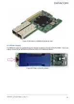
Page 24: ...2x25Gbit s Mezzanine Card 2 2 9 Power Supply The DM SV01 power is supplied through a connector located on the rear end of the SLED The power supply connector type and board location are shown in the f...

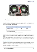
Page 25: ...m will be triggered forcing the CPUs to lower their operating frequency in order to decrease overall system power Additionally if the system power exceeds a predefined critical threshold e g a board s...

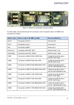
Page 26: ...Temperature VRM P0 VDD CORE RUN Voltage Regulator Module 1 CPU P0 Core Power VRM2 Temperature VRM P0 VDD SOC RUN Voltage Regulator Module 1 CPU P0 SoC Power VRM3 Temperature VRM P0 VDD MEM ABCD SUS V...

Page 27: ...re PCIE CARD SLOT3 Temperature of the PCIe card from riser card slot 3 when connected Table 11 DM SV01 temperature sensors description Additionally the DM SV01 is also capable of monitoring the system...

Page 28: ...e BMC web management interface please refer to the BMC User Manual 1 2 2 11 X24 Expansion Slot The DM SV01 server has a proprietary connector with 24 PCIe lanes used for equipping an expansion riser c...

Page 29: ...lot 2 PCIe x8 used to plug in a standard non hot pluggable PCIe x8 GEN3 or below cards This slot can have the PCIe lanes bifurcated on BIOS to the following options 1x PCIe x8 2x PCIe x4 Slot 3 PCIe x...

Page 30: ...or PCIe normal power slots PCIe x8 x16 normal power V V I A P W Total W 3 3V Aux 3 3 0 375 1 2375 36 34 3 3V 3 30 3 9 9 12V x4 x8 x16 12 00 2 1 25 2 Table 13 PCIe Normal Power slots The table below sh...

Page 31: ...IOS to the following options 1x PCIe x8 2x PCIe x4 Slot 2 PCIe x8 used to plug in a standard non hot pluggable PCIe x8 GEN3 or below cards This slot can have the PCIe lanes bifurcated on BIOS to the f...

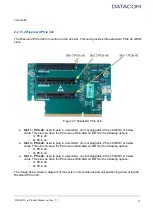
Page 32: ...36 34 3 3V 3 30 3 9 9 12V x4 x8 x16 12 00 2 1 25 2 Table 15 PCIe Normal Power slot The Risercard PCIe 3x8 does not support PCIe cards that require an extra external power connector 2 2 11 3 2x E1 S PC...

Page 33: ...hotplug capability for each SSD slot so they can be freely inserted or removed without the need to previously configure the server or inform the operating system There are two types of 2xE1 S adapter...

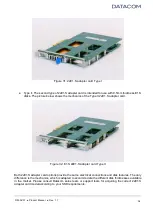
Page 34: ...II 2xE1 S adapter card Figure 32 E1 S 2xE1 S adapter card Type II Both 2xE1 S adapter card options provide the same electrical connections and disk features The only difference is the mechanics which...

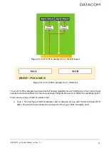
Page 35: ...e x8 slot One 2x E1 S PCIe Adapter Card Risercard PCIe x16 x8 up to two 2x E1 S PCIe Adapter Cards can be plugged into the riser card providing support for up to 4 E1 S SSDs Slot 2 PCIe x8 slot One 2x...

Page 36: ...to the SSD The table below shows the power specifications for each E1 S SSD slot of the 2xE1 S PCIe Adapter Card 2x E1 S PCIe Adapter Card slot V V I A P W Total W Slot A 12 1 12 24 Slot B 12 1 12 Ta...

Page 37: ...is equipped in the x16 expansion slot and that provides four E1 S SSD slots The Cage E1 S pinout is proprietary and it can not be used in systems other than DM SV01 The four SSD slots follow Intel s E...

Page 38: ...ture below shows the mechanics of the Type II cage E1 S Figure 38 Cage E1 S Type II Both Cage E1 S options provide the same electrical connections and disk features The only difference is the mechanic...

Page 39: ...re 39 E1 S Cage Block Diagram The Cage E1 S provides full hotplug capability for each SSD slot so they can be freely inserted or removed without the need to previously configure the server or inform t...

Page 40: ...tal W SSD Slot 1 12 1 12 48 SSD Slot 2 12 1 12 SSD Slot 3 12 1 12 SSD Slot 4 12 1 12 Table 17 E1 S Cage Power 2 2 13 TPM module The DM SV01 motherboard has a slot for connecting a proprietary TPM Trus...

Page 41: ...appropriate end of the strap to a known ground and attach the other end of the strap to your wrist When performing any installation or service procedure place static sensitive parts such as expansion...

Page 42: ...y can be freely inserted and removed even if the system is powered up The power demanded by the sleds is equally divided between all the available power supplies The number of power supplies and its r...

Page 43: ...lation 3 2 2 1 Installation facilities The installation rules below must be followed when choosing the location where the equipment will be installed Choose a location with easy access to the equipmen...

Page 44: ...ms of the rack The four brackets must be placed on the same height level in the rack and all of them must face the inside of the rack Use M5 type screws Figure 45 DM1904 fixing brackets mount 2 Positi...

Page 45: ...d and that free space of at least 10cm on the front and rear panels are respected Figure 47 DM1904 ventilation diagram 3 2 2 4 Installing Power Supplies in the DM1904 The installation of the PSUs in t...

Page 46: ...grounding point of the DM1904 Chassis is located on the right side of the back of the chassis and must always be installed The grounding point location is shown in the figures below Figure 49 DM1904 g...

Page 47: ...other structures of the set Figure 51 Inserting the DM SV01 into the DM1904 3 Release the lock pin The DM SV01 server will be mechanically locked to the shelf 4 As soon as the insertion is complete th...

Page 48: ...DM SV01 Product Manual Rev 1 1 48 Figure 52 Removing DM SV01 from the DM1904...

Page 49: ...ystem is ready to turn the CPUs on as explained in section 4 3 This condition is indicated by a BMC LED Yellow keeps flashing slowly indicating the BMC is running b PWR_STBY LED stops blinking and tur...

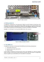
Page 50: ...e motherboard as shown below Figure 53 LAN Connector 2 Through the Mezzanine Card using the NC SI interface The NC SI or network controller sideband interface is an electrical interface and protocol t...

Page 51: ...condition is indicated by the following behaviors a The BMC LED yellow keeps flashing slowly 2Hz indicating that the BMC is operational b PWR_STBY LED remains on in blue color indicating that the STAN...

Page 52: ...is to use the front panel interfaces to connect a standard VGA monitor and typical USB mouse and keyboard devices Details of these interfaces can be found in sections 2 2 3 and 2 2 4 If desired press...

Page 53: ...t least 4s b BMC WEB management interface in the BMC WEB management interface access the Control Server Power Operations menu mark the Immediately option and then click on SHUTDOWN Using any of the op...

Page 54: ...d DDR memories and it is designed for efficiently guiding the airflow in order to refrigerate such components The insertion and removal of the air duct can be accomplished by following the procedures...

Page 55: ...s all available configurations for single dual and quad rank RDIMMs according to the AMD guidelines The DIMM capacities are 8GB 16GB 32GB 64GB 128GB and 256GB per module The table below lists the avai...

Page 56: ...per processor the user has still the following option If the processors have up to 32 cores each the user may install four DIMM modules on slots C D G and H The server performance may be reduced when...

Page 57: ...ides until the levers of the connector move up and attach to the module s side chamfer Figure 61 DIMM installation procedure In order to remove a DDR4 module from the DIMM slot please follow the instr...

Page 58: ...the DDR4 module by its edges and pull it away from the connector 5 3 M 2 SSD Installation The installation procedure for the M 2 SSD is described below 1 insert the M 2 card into the connector using a...

Page 59: ...Figure 64 M 2 standoff fixing The plastic standoff that holds the far end of the M 2 card may have its position changed in order to adapt the connection to the 2280 or 22110 form factor as needed by...

Page 60: ...A and B and the four fixing holes Figure 66 Mezzanine card installation 2 Press the Mezzanine Card down to attach both connectors Some mezzanine card models may have just one connector on side B The...

Page 61: ...rting the mechanics for the riser cards 1 Position the mechanics over the motherboard as shown in the Figure 68 aligning the chamfers with the guiding pins of the baseplate Figure 69 and Figure 70 and...

Page 62: ...nually or using a screwdriver Figure 71 Riser cards mechanics installation In order to remove the mechanics for the riser cards from the baseplate please follow the procedure below 1 Loosen the screw...

Page 63: ...rd options is identical Note in order to install a riser card in the DM SV01 server the mechanics for the riser cards must be previously installed Please refer to section 5 5 1 Riser Cards mechanics f...

Page 64: ...mainboard slot connector until the riser card guiding holes are completely positioned on the fixing guide pins Make sure that the riser card is vertically aligned when moving it down Figure 74 Riser c...

Page 65: ...th hands and pull it up vertically until it is completely removed from the connector 5 5 2 1 PCIe cards installation The following procedure must be followed for installing a standard PCIe card at any...

Page 66: ...rd PCIe 3x8 please follow the procedure below 1 Remove the screw that fixes the front panel of the PCIe card to the riser cards mechanics 2 Manually disconnect the PCIe connector from the riser card s...

Page 67: ...S over the DM SV01 server according to Figure 78 3 Move the cage E1 S down towards the mainboard slot connector until the connection is accomplished Make sure that the cage E1 S is vertically aligned...

Page 68: ...S disk into both the Cage E1 S and the 2xE1 S PCIe adapter card For inserting an E1 S disk in the server please refer to the procedure below 1 Position the E1 S disk in the slot you would like to inse...

Page 69: ...stem remove the DM SV01 server from the shelf Remove the air duct as explained in section 5 1 Disconnect the fan connector by pulling it up caution disconnect the fan by holding the white connector do...

Page 70: ...Figure 83 fan removal Insert the replacing fan into the mechanics aligning the four fixing rubbers to the respective holes step 1 and then move the fan down until the fixing rubbers are well attached...

Page 71: ...or into the motherboard Please pay attention to the mechanical polarization of the connector which defines the right side of the connection Figure 86 Inserting the fan connector Insert the air duct as...

Page 72: ...om the Normal position and place it in the CLEAR CMOS position please see Figure 87 Wait for approximately 10 seconds 4 Remove the jumper from the CLEAR CMOS position and place it back in the Normal p...

Page 73: ...emove the battery from the holder step 2 Figure 88 Battery removal In order to insert the CMOS battery please follow the instructions below 1 Insert the CR2032 battery in the holder with the positive...

Page 74: ...oard battery is installed with reversed polarity This battery must be replaced only by an equivalent type CR2032 Please consult the Datacom support team if you have any doubt about the battery specifi...

Page 75: ...herboard can be inserted or removed from the baseplate if needed The procedure for inserting the motherboard in the baseplate is described below 1 Position the motherboard over the baseplate aligning...

Page 76: ...FANs using the procedure described in section 5 7 Fans installation Figure 92 Motherboard installation In order to remove the motherboard from the baseplate the procedure below must be followed 1 Loo...

Page 77: ...ODs are a mature and stable technology that does not advance at the same pace as servers Unlike equipment where storage is located inside servers your investment in JBODs will not be discarded in the...

Page 78: ...ernal unit for GPU cards offers all the advantages of a disaggregated solution Those units are connected to the DM SV01 through PCIe interface extenders and coaxial copper cables the same used for ext...

Page 79: ...DM SV01 Product Manual Rev 1 1 79 7 References 1 DM SV01 Server BMC User Manual 2 DM SV01 Server BIOS User Manual 3 DM SV01 Technical File CE Marking...

Page 80: ...W Efficiency Score 43 8 Performance Score 9 83 Table 22 DM SV01 low end configuration specification Item Quantity Description Power W Base value Motherboard base value 40W CPU additional power 7 627 o...

Page 81: ...2 Performance Score 50 53 Table 24 DM SV01 high end configuration specification Item Quantity Description Power W Base value Motherboard base value 40W CPU additional power 33 096 of transactions per...

Page 82: ...duct Manual Rev 1 1 82 8 3 A 3 Operating Condition Classification The operating condition of DM SV01 is classified as an A3 type as shown in the figure below Figure 95 DM SV01 operating condition clas...

Page 83: ...other hand is good for everyday use and testing and it is usually much faster than sanitize operation 9 1 B 1 Format The nvme format can be achieved by the following command on the operating system wi...

Page 84: ...cli installed nvme sanitize a option device Where the a parameter is defined as follows a action Sanitize Action 0 Reserved 1 Exit Failure Mode 2 Start a Block Erase sanitize operation 3 Start an Over...

Page 85: ...below Figure 96 DM SV01 buttons location top view Figure 97 DM SV01 buttons front view The buttons of the DM SV01 server are listed in the table below Button Function Prerequisites Action required Ser...

Page 86: ...mplete the PWR_ACT LED will turn off indicating that the host processor is in Standby mode Reset Button Reset the host processors Host processors are powered up Press the reset button shortly The PWR_...

Page 87: ...e below LED LED Color Information Power Standby OFF There is no power 12V at the rear power input connector Solid RED System failure Blinking BLUE System is initializing and waiting for BMC boot to co...

Page 88: ...ail OFF No failure Solid RED System failure requires system servicing User ID OFF Unit ID function is turned OFF Blinking GREEN Unit ID function is turned ON BMC Fast Blinking YELLOW BMC initializatio...

Page 89: ...uct Manual Rev 1 1 89 This document comprises 89 pages Revision History Date Description 05 08 2022 Release 1 0 25 11 2022 Release 1 1 Section 5 8 Battery and Clear CMOS corrected CMOS battery polarit...

Reviews: