


Connecting Signals
27
4
4
4
4
4
4
4
4
4
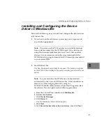
2.
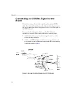
Attach EP306 connector 0 (VID0_IN), 1 (VID1_IN), or 2
(VID2_IN) to the video source’s composite video output
connector.
Note:
The EP306 attaches to female BNC connectors. If the video
out connector on your video input source is a male BNC or an
RCA connector, you need to obtain the appropriate adaptor
(available at electronic equipment stores).
3.
Connect additional composite video sources, if desired, to the
unused video input connectors: 0 (VID0_IN), 1 (VID1_IN), or 2
(VID2_IN).
4.
If you want the board to provide a horizontal sync to the video
source, attach the horizontal sync input of the video source to the
output of EP306 connector 8 (HSYNC_OUT).
5.
If you want the board to provide a vertical sync to the video
source, attach the vertical sync input of the video source to the
output of EP306 connector 9 (VSYNC_OUT).
6.
If you want the board to provide a composite sync to the video
source, attach the composite sync input of the video source to the
output of EP306 connector 10 (CSYNC_OUT).
7.
If you are using an external trigger source, attach EP306
connector 7 to the output of the external trigger source.
8.
If you are using digital I/O signals, attach EP306 connectors 4, 5,
6, and/or 11, to the external device’s digital I/O lines.
Summary of Contents for DT3153
Page 1: ...DT3153 UM 18227 D Getting Started Manual...
Page 8: ...About this Manual viii...
Page 9: ...1 1 Overview Key Hardware Features 2 DT3153 Software 3 Getting Started Procedure 4...
Page 24: ...Chapter 2 16...
Page 38: ...Chapter 4 30...
Page 54: ...Chapter 5 46...
Page 55: ...47 6 Verifying Board Operation Overview 49 Installing DT Acquire 50 Using DT Acquire 51...
Page 62: ...Chapter 6 54...


