background image

Chapter 5

44

14.

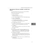
Enter a board name (alias), which can be any name you choose, 
and click 

Add

. The board name is used by supported software, 

such as DT-Acquire and the Frame Grabber SDK. Only one name 
(alias) per installed board is allowed.

The DT3152-LS Configuration dialog box appears.

15.

On the 

General 

tab of the DT3152LS Configuration dialog box, 

click 

Enable Board 

to activate the board.

If you want to retain the settings but disable the board, remove the 
checkmark next to Enable Board.

16.

To configure the board for area-scan (two-dimensional) 
operations, perform the following steps:

a.

On the 

General 

tab of the DT3152LS Configuration dialog 

box, click

 Enable 2 Dimensional Mode

.

b.

Click the 

2 Dimension 

tab of the DT3152LS Configuration 

dialog box. 

c.

For 

Video Format

, indicate the video format that you want 

for the default setting by clicking 50 Hz or 60 Hz.

d.

For 

Memory Size

, select the amount of memory (in MB) that 

you want to allocate in your system to hold the acquired 
frames. A 60 Hz, 640-by-480 image requires 308 KB per 
frame; a 50 Hz, 768-by-576 image requires 443 KB per frame. 
The upper limit depends on your system’s resources.


The 

recommended minimum is 1 MB.

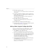
17.

To configure the board for line-scan (one-dimensional) 
operations, perform the following steps:

a.

Click the 

General 

tab of the DT3152LS Configuration dialog 

box, then click

 Enable Line Scan Mode

.

b.

Click the 

Line Scan 

tab of the DT3152LS Configuration 

dialog box.

c.

Enter the number of 500 KB FIFO buffers to use. A typical 
number of FIFO buffers is 9.

The default is 0. If, when running your program, you encounter 
overflow errors, increase the number of FIFO buffers.

Summary of Contents for DT3152-LS

Page 1: ...UM 16398 D DT3152 LS Getting Started Manual...

Page 2: ...gements of patents or other rights of third parties which may result from its use No license is granted by implication or otherwise under any patent rights of Data Translation Inc Use duplication or d...

Page 3: ...r 2 Preparing to Use the DT3152 LS 7 Unpacking 9 Checking the System Requirements 10 Configuring Jumper W1 12 Installing the Software 13 Installing the DT3152 LS Documentation 14 Viewing the DT3152 LS...

Page 4: ...950B or 4 00 950 C Starts 37 After Windows 95 Version 4 00 950B or 4 00 950 C Has Started 39 Adding a Board using the Configuration Utility 40 Installing and Configuring the Device Driver in Windows 9...

Page 5: ...ing DT Acquire 65 Performing an Area Scan Operation 66 Performing a Passthru Operation 67 Using LS Acquire 68 Performing a Line Scan Acquisition 69 Performing a Continuous Line Scan Passthru Operation...

Page 6: ...Contents vi...

Page 7: ...dition Windows NT 4 0 Windows 2000 or Windows XP operating system What You Should Learn from this Manual This manual will help you install and set up your board and device driver successfully It is or...

Page 8: ...age to yourself or your equipment Items that you select or type are shown in bold Courier font is used to represent source code Related Information Refer to the following documents for more informatio...

Page 9: ...s Manual UM 17755 and DT Vision Foundry API Manual UM 17757 available from Data Translation describe how to use DT Vision Foundry to create machine vision applications using object oriented image pro...

Page 10: ...About this Manual x...

Page 11: ...1 1 Overview Key Hardware Features 2 DT3152 LS Software 4 Getting Started Procedure 5...

Page 12: ...with as many lines as the system memory allows Digitizes 8 bit monochrome video from any one of four video input channels Supports asynchronous reset cameras In area scan mode synchronizes to any one...

Page 13: ...AC coupled signals Provides programmable A D reference offset and gain 0 5 1 2 and 4 settings to adjust black and white levels and In line scan mode accepts four TTL level digital input signals for g...

Page 14: ...e driver to use the DT3152 LS board with any of the supported software packages or utilities DT3152 LS User s Manual in PDF format Describes the features of the DT3152 LS board and how to use the DT31...

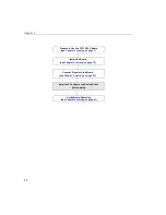
Page 15: ...the diagram shows you where you are in the getting started procedure Figure 1 Getting Started Flow Diagram Install the Board see Chapter 3 starting on page 19 Connect Signals to the Board see Chapter...

Page 16: ...Chapter 1 6...

Page 17: ...aring to Use the DT3152 LS Unpacking 9 Checking the System Requirements 10 Configuring Jumper W1 12 Installing the Software 13 Installing the DT3152 LS Documentation 14 Viewing the DT3152 LS Documenta...

Page 18: ...nstall the Board see Chapter 3 Connect Signals to the Board see Chapter 4 Verify Board Operation see Chapter 6 Install and Configure the Device Driver see Chapter 5 Prepare to Use the DT3152 LS Board...

Page 19: ...Service Department at 508 481 3700 x394 Customer Service will guide you through the appropriate steps for replacing missing or damaged items If you are located outside the USA call your local distrib...

Page 20: ...ork properly Triton 8243xFX Triton2 8243xHX Triton VX 8243xVX Triton TX 8243xTX Natoma 8244xFX or Natoma 8244xLX Note The following Intel PCI chip sets are known not to work properly Saturn 8242x Merc...

Page 21: ...ersion 4 release 6 At least one available PCI 32 bit or 64 bit bus master expansion slot At least 16 MB of RAM Note that 300 KB 60 Hz or 432 KB 50 Hz are required to store each two dimensional frame A...

Page 22: ...n the board Figure 2 Location of Jumper W1 on the DT3152 LS Board To install the jumper perform the following steps 1 Discharge any static electricity by holding the wrapped board in one hand while pl...

Page 23: ...rive 4 Click OK The Imaging OMNI CD splash screen appears 5 Click Install Products 6 Click Mach I Series 7 Click Device Drivers 8 Click DT3152LS then click Next If you are using Windows NT 4 0 Windows...

Page 24: ...LS documentation 1 Insert the Imaging OMNI CD into your CD ROM drive 2 Click Start from the Task Bar then click Run The Run dialog box appears 3 In the Command Line edit box enter x LAUNCH EXE where x...

Page 25: ...2 2 15 Browse to the directory in which to copy the manual on your hard disk the click Next The manual is copied to your hard disk 16 Click OK 17 Click Main Menu then click Exit Refer to the next sec...

Page 26: ...you can view these documents by accessing them through the Data Translation Inc DT3152LS program folder You can also view the documents from the Imaging OMNI CD by performing the following steps 1 Ins...

Page 27: ...om a hand to an index finger To go back to the page from which the jump was made click the right mouse button and Go Back or from the main menu click Document then Go Back To print the document from t...

Page 28: ...Chapter 2 18...

Page 29: ...19 3 Installing the Board Setting up the Computer 21 Selecting an Expansion Slot 22 Inserting the DT3152 LS Board in the Computer 23...

Page 30: ...ignals to the Board see Chapter 4 starting on page 25 Verify Board Operation see Chapter 6 starting on page 61 Install and Configure the Device Driver see Chapter 5 starting on page 31 Prepare to Use...

Page 31: ...so on connected to the computer 3 Unplug the computer and all peripherals 4 Remove the cover from you computer Refer to your computer s user manual for instructions Next select an expansion slot as de...

Page 32: ...ree PCI slots one of which may be a shared ISA PCI slot are available If an ISA board exists in the shared slot you cannot use the slot for a PCI board likewise if a PCI board exists in the shared slo...

Page 33: ...hassis 2 Carefully remove the antistatic packing material from the board We suggest that you save the original packing material in the unlikely event that your board requires servicing in the future 3...

Page 34: ...6 Secure the board in place at the rear panel of the system unit using the screw removed from the slot cover When you are finished with this procedure continue by connecting signals to the board Refer...

Page 35: ...25 4 Connecting Signals Connecting Signals to Connector J1 on the Board 27 Connecting Signals to Connector J2 on the Board 29...

Page 36: ...ION Always turn off the power to both your computer and the input device before making these connections Damage can result if connections are made with the power on Install the Board see Chapter 3 Con...

Page 37: ...the DT3152 LS board as shown in Figure 4 and tighten the screws on the connector Figure 4 Connecting the EP306 Cable Assembly to Connector J1 2 If you are using AC coupled video sources connect a vide...

Page 38: ...or available at electronic equipment stores 3 For two dimensional images area scan attach a composite sync input to any unused EP306 video input connector 0 1 2 or 3 if desired 4 If you are using an e...

Page 39: ...to connector J2 on the DT3152 LS board perform the following steps 1 After making sure power to the computer is off push the 15 pin connector of the second EP306 cable assembly into the J2 socket at...

Page 40: ...r 4 connect the positive line sync output signal on the line scan camera to EP306 connector 5 5 Connect the negative clock input jack of the line scan camera to EP306 connector 6 connect the positive...

Page 41: ...er in Windows 95 34 Installing and Configuring the Device Driver in Windows 98 43 Installing and Configuring the Device Driver in Windows Me 46 Installing and Configuring the Device Driver in Windows...

Page 42: ...on page 19 Connect Signals to the Board see Chapter 4 starting on page 25 Verify Board Operation see Chapter 6 starting on page 61 Install and Configure the Device Driver this chapter Prepare to Use...

Page 43: ...ith any application developed using the 32 bit Frame Grabber SDK which follows the DT Open Layers Application Programming Interface API standards Before installing the software ensure that you have In...

Page 44: ...tab if necessary The version of Windows 95 is listed under System Note To provide Direct Draw support the Imaging OMNI CD contains the following files ddraw dll ddraw16 dll and ddhelp exe Windows not...

Page 45: ...MNI CD into the CD ROM drive 4 Click Browse browse to x DRIVERS DT3152LS Win95 where x is the letter of your CD ROM drive then click OK 5 When the files have been copied remove the CD ROM from the CD...

Page 46: ...pears 5 Click PCI Multimedia Video Device then click Remove The Confirm Device Removal dialog box appears 6 Click OK to remove the device 7 If multiple PCI Multimedia Video Devices are installed repea...

Page 47: ...DT3152 LS board 17 Follow the steps on page 40 to add the new DT3152 LS board to the DT3152 LS Device Driver configuration Installing the Device Driver Under Version 4 00 950B or 4 00 950 C of Windows...

Page 48: ...are being copied 5 When the files have been copied remove the CD ROM from the CD ROM drive You are prompted to restart your system 6 Click Yes to restart the system For proper operation it is very imp...

Page 49: ...7 If multiple PCI Multimedia Video Devices are installed repeat steps 3 to 6 to remove all PCI Multimedia Video Devices 8 Click Refresh The New Hardware Found dialog box appears followed by the Update...

Page 50: ...add the new DT3152 LS board to the DT3152 LS Device Driver configuration Adding a Board using the Configuration Utility To add a new DT3152 LS board to the DT3152 LS Device Driver configuration at sy...

Page 51: ...frame a 50 Hz 768 by 576 image requires 443 KB per frame The upper limit depends on your system s resources The recommended minimum is 1 MB 5 To configure the board for line scan one dimensional oper...

Page 52: ...DT3152 LS configuration The DT3152 LS Configuration COMPLETE dialog box appears 8 Click OK 9 Click OK to restart the system The system automatically restarts so that the changes take effect Once you...

Page 53: ...g OMNI CD into the CD ROM drive 7 Click Browse browse to x DRIVERS DT3152LS WIN98 where x is the letter of your CD ROM drive and click OK 8 Click Next The name of the device driver is displayed 9 Clic...

Page 54: ...152LS Configuration dialog box c For Video Format indicate the video format that you want for the default setting by clicking 50 Hz or 60 Hz d For Memory Size select the amount of memory in MB that yo...

Page 55: ...LS Device Driver Configuration dialog box reappears you can see the name of the board you just added 19 Click Close to end the DT3152 LS configuration The DT3152 LS Configuration COMPLETE dialog box a...

Page 56: ...ystem are using the same interrupt that the DT3152 LS board is using and ensure that PCI interrupts are enabled in your system BIOS 2 Start Windows Me The Add Hardware Found dialog box appears 3 Click...

Page 57: ...the board for area scan two dimensional operations perform the following steps a On the General tab of the DT3152LS Configuration dialog box click Enable 2 Dimensional Mode b Click the 2 Dimension ta...

Page 58: ...at the same time However to maximize system memory enable only one mode at a time 17 Click Done The DT3152 LS Configuration dialog box is redisplayed you can see the name of the board you just added...

Page 59: ...e Imaging OMNI CD into the CD ROM drive and enter x DRIVERS DT3152LS WINNT where x is the letter of your CD ROM drive 8 Click OK The Add Unlisted or Updated Driver dialog box appears 9 Click OK 10 Cli...

Page 60: ...equires 443 KB per frame The upper limit depends on your system s resources The recommended minimum is 1 MB 15 To configure the board for line scan one dimensional operations perform the following ste...

Page 61: ...added 17 Click Close to finish A dialog box appears indicating that you need to restart Windows NT for the changes to take effect 18 Restart your system to cause the new configuration to take effect...

Page 62: ...he section on disabling the device and continue with the instructions on page 53 Disabling the Device You need to disable the device so that Windows 2000 does not reidentify the board every time the s...

Page 63: ...click Next 6 Click Sound video and game controllers then click Next 7 Click Have Disk 8 Insert the Imaging OMNI CD into your CD ROM drive 9 Browse to the Drivers DT3152LS Win2K directory on the Imagi...

Page 64: ...or 60 Hz d For Memory Size select the amount of memory in MB that you want to allocate in your system to hold the acquired frames A 60 Hz 640 by 480 image requires 308 KB per frame a 50 Hz 768 by 576...

Page 65: ...an mode at the same time However if you want to maximize system memory enable only one mode at a time 21 Click OK The DT3152 LS Configuration dialog box reappears you can see the name of the board you...

Page 66: ...ice so that Windows XP does not reidentify the board every time the system is restarted To disable the device perform the following steps 1 Start Windows XP with administrative rights The Found New Ha...

Page 67: ...e about hardware connection appears 3 Select Yes I have already connected the hardware then click Next 4 Scroll through the list and select Add a new hardware device then click Next 5 Select Install t...

Page 68: ...box click Enable 2 Dimensional Mode b Click the 2 Dimension tab of the DT3152LS Configuration dialog box c For Video Format indicate the video format that you want for the default setting by clicking...

Page 69: ...he DT3152LS Configuration dialog box you can enable the board for both 2 Dimensional Mode and Line Scan mode at the same time However if you want to maximize system memory enable only one mode at a ti...

Page 70: ...Chapter 5 60...

Page 71: ...61 6 Verifying Board Operation Overview 63 Installing DT Acquire or LS Acquire 64 Using DT Acquire 65 Using LS Acquire 68...

Page 72: ...on page 19 Connect Signals to the Board see Chapter 4 starting on page 25 Verify Board Operation this chapter Install and Configure the Device Driver see Chapter 5 starting on page 31 Prepare to Use...

Page 73: ...connected and that you can acquire images DT Acquire allows you to Acquire a two dimensional frame of video information area scan to system memory Display the area scan image live in passthru mode Ope...

Page 74: ...n appears 4 Click Install Products 5 Click Mach I Series 6 Click DT Acquire if you want to install DT Acquire or click LS Acquire if you want to install LS Acquire 7 Click Next The default installatio...

Page 75: ...ng DT Acquire If you have any trouble performing any of these operations refer to the Troubleshooting chapter of the DT3152 LS User s Manual refer to page 14 for information on installing and viewing...

Page 76: ...n menu click Run then Single Frame Acquire A single frame is acquired synchronously and displayed on the screen 6 To acquire another frame repeat step 5 7 If you wish modify the parameters available f...

Page 77: ...m the DT Acquire main menu click Run then Start Pass Thru Live video is asynchronously acquired to display memory converted to bitmap format and displayed on the screen 5 To stop the asynchronous pass...

Page 78: ...uire If you have any trouble performing any of these operations refer to the Troubleshooting chapter of the DT3152 LS User s Manual refer to page 14 for information on installing and viewing this manu...

Page 79: ...T3152 LS board when you configured the device driver 5 Change the parameter settings to match the requirements of your camera 6 Click Acquire The number of lines specified in the list of parameters is...

Page 80: ...when you configured the device driver 5 Change the parameter settings to match the requirements of your camera 6 Click Start Pass Lines are continuously acquired and displayed on the screen 7 To stop...

Page 81: ...98 procedures 43 Windows Me procedures 46 Windows NT 4 0 procedures 49 Windows XP procedures 56 DT3152 LS documentation installing 14 DT Acquire installing 64 using 65 E EP306 cable 26 expansion slot...

Page 82: ...cuments viii requirements 10 resolution video adapter 68 S selecting an expansion slot 22 setting up the computer 21 slot selection 22 system requirements 10 U unpacking the board 9 V verifying board...

Page 83: ...00 950 or 4 00 950a 35 installing the device driver at startup version 4 00 950B 37 Windows 98 installing the device driver 43 Windows Me installing the device driver 46 Windows NT 4 0 installing the...

Page 84: ...Index 74...

Reviews: