


10
In pLAN network, both the dap4 controller and the display have separate addresses. “Display Ad-
dress” is he address of the display and I/O Board Address is the address of the dap4 controller.
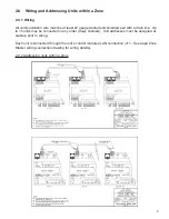
In a Zone Master network where all units are connected via pLAN, each unit and its display must
have different addresses. Below is the recommendation addresses combination:
Table 1: Recommended Addresses in Zone Master control
Unit 1
Unit 2
Unit 3
Unit 4
Unit 5
Unit 6
Unit 7
Unit 8
dap4 pLAN address
1
2
3
4
5
6
7
8
Display Address
32
31
30
29
28
27
26
25
Unit 9
Unit 10
Unit 11
Unit 12
Unit 13
Unit 14
Unit 15
Unit 16
dap4 pLAN address
9
10
11
12
13
14
15
16
Display Address
24
23
22
21
20
19
18
17
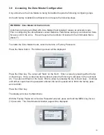
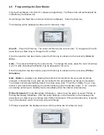
2.0.3 Changing the address of the dap4 controller:
Since all units will be shipped as Unit #1, a change of Controller Addresses needs to be done in
order to establish a Zone Master communication.
Follow this procedure to set pLAN address to each dap4 controller in the zone:
• Press button A for 5 seconds by using a small screw driver or a small pin. The pLAN ad-
dress will start fl ashing.
• Press repeatedly or hold the button until reaching the required address (2, 3, 4…16).
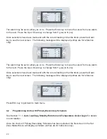
Note:
You can set up dap4 address from 1 - 16. Address 17 to 32 are reserved for display mod-
ules. Follow the table on previous page to set the display module address.
• Wait until the address starts fl ashing rapidly. In this stage the address has been saved but it
not yet active for the application program. Power down the controller.
• Power up the controller again. The address is now set to the dap4
Figure 1: Address pin on dap4 controller
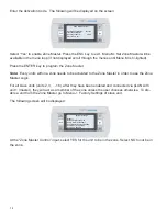
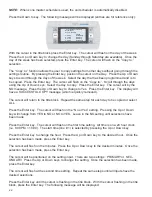
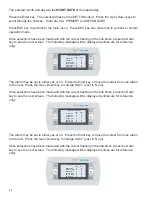
2.0.3.1
Changing the Address of the Mini dap4
Change the display module address to 00 by holding three buttons (UP+ENTER+DOWN) at the
same time. A screen will appear showing addresses of the display terminal and I/O board. Use


