PCIe-AIO14 User Manual (Rev 1.2)
- 5 -
http://www.daqsystem.com
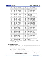
19
#14 Input (-), AINN14
53
Analog Ground, AGND
20
#14 Input (+), AINP14
54
Digital Output, DOUT1
21
#12 Input (-), AIN12
55
Analog Ground, AGND
22
#12 Input (+), AINP12
56
Digital Output, DOUT2
23
#10 Input (-), AINN10
57
Analog Ground, AGND
24
#10 Input (+), AIN10
58
Digital Output, DOUT3
25
#8 Input (-), AINN8
59
Analog Ground, AGND
26
#8 Input (+), AINP8
60
Digital Ground, GND
27
#6 Input (-), AINN6
61
Analog Ground, AGND
28
#6 Input (+), AINP6
62
Digital Ground, GND
29
#4 Input (-), AINN4
63
Analog Ground, AGND
30
#4 Input (+), AINP4
64
Digital Ground, GND
31
#2 Input (-), AINN2
65
Analog Ground, AGND
32
#2 Input (+), AINP2
66
Reserved
33
#0 Input (-), AINN0
67
Analog Ground, AGND
34
#0 Input (+), AINP0
68
Reserved
★
Please inquire about the availability of analog input cable and terminal block board when
you purchase the product.
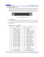
3.2.2 Connector J2
The 16-bit analog differential input signals (AINP, AINN, AGND) from 16 to 31 are connected to
the 4-bit digital input and output signal. The applicable connector is HDRA-E68LFDT (Honda) or
compatible product.
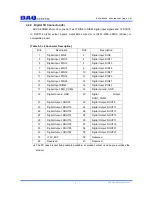
[Table 3-2. J2 Connector Description]
Pin#
Description
Pin#
Description
1
Reserved
35
Reserved
2
Analog Ground, AGND
36
Reserved
3
#31 Input (-), AINN31
37
Analog Ground, AGND
4
#31 Input (+), AINP31
38
Digital Input, DIN_COM1
5
#29 Input (-), AINN29
39
Analog Ground, AGND
6
#29 Input (+), AINP29
40
Digital Input, DIN4
7
#27 Input (-), AINN27
41
Analog Ground, AGND
8
#27 Input (+), AINP27
42
Digital Input, DIN5
9
#25 Input (-), AINN25
43
Analog Ground, AGND
10
#25 Input (+), AINP25
44
Digital Input, DIN6


