


P
AGE
12
46034-0997 <90-00030>
2. Set the straps and switches.
Set the straps by removing the power supply. Remove the three
retaining screws from the subassembly and carefully pull the
subassembly out of its connections.
Once strapping had been verified or corrected, replace the power
supply subassembly by aligning the module connector pins with
the subassembly connector pins. Gently press the power supply
into place. Install the three retaining screws.
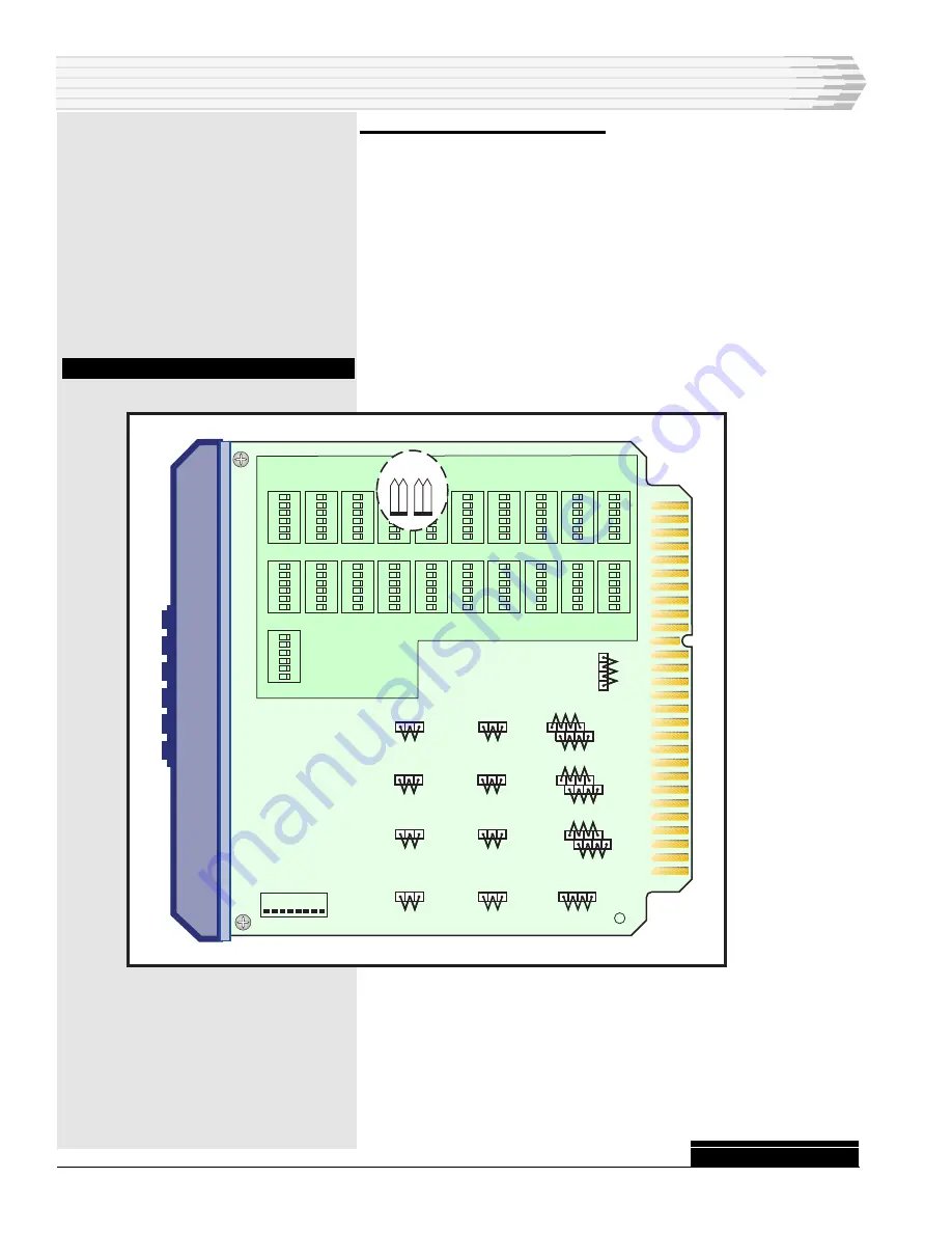
Refer to Fig. 7 and Tables C and D for setting straps and
switches.
F
IG
. 7 - S
WITCH
AND
S
TRAP
L
OCATIONS
INSTALLATION
CONTINUED
. . .
1234
5
6
ON
1234
5
6
ON
1234
5
6
ON
1234
5
6
ON
1234
5
6
ON
1234
5
6
ON
1234
5
6
ON
1234
5
6
ON
1234
5
6
ON
1234
5
6
ON
1234
5
6
O
1234
5
6
ON
1234
5
6
O
1234
5
6
ON
1234
5
6
ON
1234
5
6
ON
1234
5
6
ON
1234
5
6
ON
1234
5
6
ON
1234
5
6
ON
1234
5
6
O
S17 S18
S1
XX
XX
S4
S5
S6
S7
S8
S19 S20 S9
S10 S11 S12 S13 S14 S15 S16
S21
D
1 2
C
1 2
3A
2A
2 1 3
2 1 3
5A
4A
2 1 3
6A
2 1 3
1A
2 1 3
2B
1 2
4B
1 2
6B
1 2
8B
1 2
1B
1 2
3B
1 2
5B
1 2
7B
1 2
3
1
2
S22
1
8
8A
7A