


46034-0997 <90-00030>
P
AGE
11
INSTALLATION
I
nstallation consists of installing the subassembly, setting the
module straps and switches, wiring the connector, and install-
ing the module in the equipment housing.
1. Install the subassembly.
If a different subassembly is to be installed, remove the three
screws from the subassembly mounting standoffs and carefully
pull the subassembly out of its connections.
If a TTL subassembly (bypass card) was installed, remove the
blue hole plug from the front panel subassembly window.
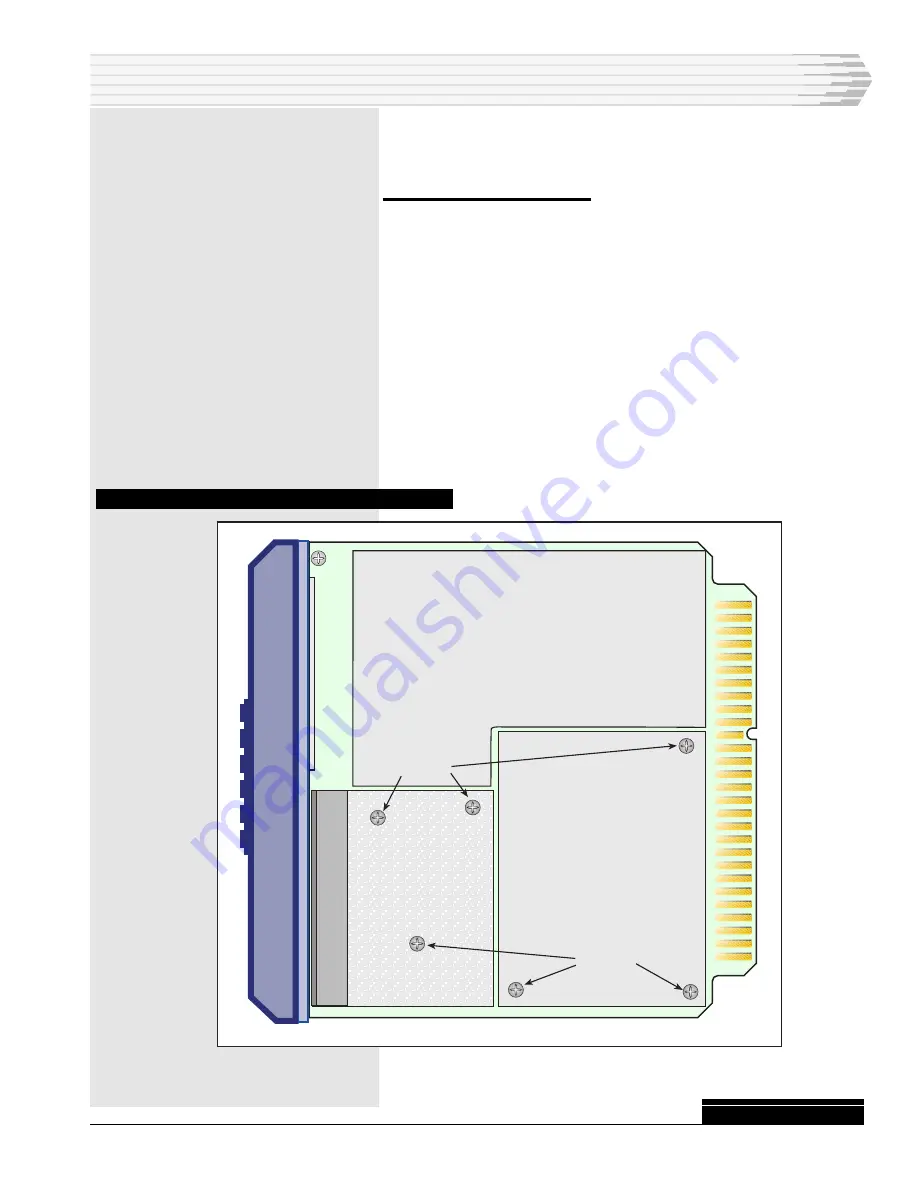
Install the new subassembly. Refer to Fig. 6. Ensure the subas-
sembly connector pins go into module receptacles J4 and J5. The
subassembly should sit down on the standoffs and the subas-
sembly front panel (except for the TTL subassembly) should
appear straight in the module front panel opening.
Reinstall the screws on the mounting standoffs.
F
IG
. 6 - S
UBASSEMBLY
AND
P
OWER
S
UPPLY
L
OCATIONS
CONTINUED
. . .
Current Loop
or
Tone Modem
Retaining
Screws
Power Supply
Retaining
Screws