


11 Specifications
Supply
Mains voltage (L1, L2, L3)
MCD5-xxxx-T5
200–525 V AC (
±
10%)
MCD5-xxxx-T7
380–690 V AC (
±
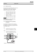
10%) (in-line connection)
MCD5-xxxx-T7
380–600 V AC (
±
10%) (inside delta connection)
Control voltage (A4, A5, A6)
CV1 (A5, A6)
24 V AC/V DC (
±
20%)
CV2 (A5, A6)
110–120 V AC (+10%/-15%)
CV2 (A4, A6)
220–240 V AC (+10%/-15%)
Current consumption (maximum)
CV1
2.8 A
CV2 (110–120 V AC)
1 A
CV2 (220–240 V AC)
500 mA
Mains frequency
45–66 Hz
Rated insulation voltage to ground
600 V AC
Rated impulse withstand voltage
4 kV
Form designation
Bypassed or continuous, semiconductor motor starter form 1
Short circuit capability (IEC)
Coordination with semiconductor fuses
Type 2
Coordination with HRC fuses
Type 1
MCD5-0021B to MCD5-0215B
Prospective current 65 kA
MCD5-0245B to MCD5-0961B
Prospective current 85 kA
MCD5-0245C to MCD5-0927B
Prospective current 85 kA
MCD5-1200C to MCD5-1600C
Prospective current 100 kA
For UL short-circuit current ratings, see Table 4.12.
Electromagnetic capability (compliant with EU Directive 89/336/EEC)
EMC emissions
IEC 60947-4-2 Class B and Lloyds Marine No 1 Specification
EMC immunity
IEC 60947-4-2
Inputs
Input rating
Active 24 V DC, 8 mA approximately
Start (15, 16)
Normally open
Stop (17, 18)
Normally closed
Reset (25, 18)
Normally closed
Programmable input (11, 16)
Normally open
Motor thermistor (05, 06)
Trip >3.6 k
Ω
, reset <1.6 k
Ω
Outputs
Relay outputs
10 A @ 250 V AC resistive, 5 A @ 250 V AC AC15 pf 0.3
Programmable outputs
Relay A (13, 14)
Normally open
Relay B (21, 22, 24)
Changeover
Relay C (33, 34)
Normally open
Analog output (07, 08)
0–20 mA or 4–20 mA (selectable)
Maximum load
600
Ω
(12 V DC @ 20 mA)
Accuracy
±
5%
24 V DC output (16, 08) maximum load
200 mA
Accuracy
±
10%
Specifications
VLT
®
Soft Starter MCD 500
82
Danfoss A/S © 05/2016 All rights reserved.
MG17K602
11
11


