-
5.
6.
7.
8.
9.
10.
-
-
-
1.
2.
-
-
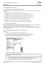
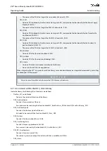
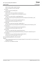
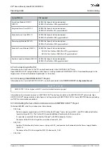
GSDML-V2.xx-Danfoss-DAM-2Port-IRT-yyyymmdd.xml
GSDML-V2.xx-Danfoss-DAM-3Port-RT-yyyymmdd.xml
Auxiliary Capacitors Module (ACM 510):
GSDML-V2.xx-Danfoss-ACM-yyyymmdd.xml
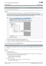
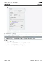
Drag the device
Danfoss Drive Servo IRT
on to an existing PROFINET
®
Ethernet network.
Find the servo drive device named
Danfoss Drive Servo IRT
by expanding the
PROFINET IO
entry in the hardware
catalog on the right side of the screen and selecting [Additional Field Devices
→
Drives
→
VLT
®
FlexMotion]. If the
device is not visible, update the hardware catalog by selecting [Options
→
Update catalog).
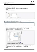
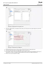
Expand
Drive Object 1
and folder
Profile
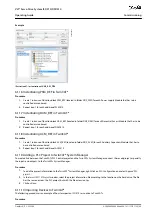
in the hardware catalog on the right side of the screen and drag the
Danfoss Tele-
gram
to the free slot of
Drive Object 1
at the bottom of the screen.
e3
0b
h5
21
.1
0
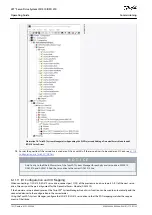
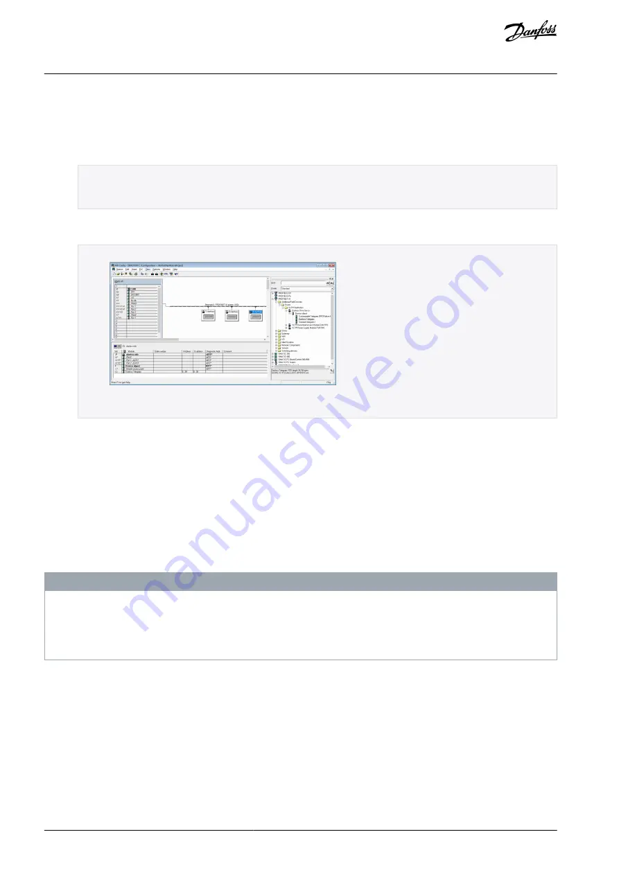
Illustration 77: Dragging the Danfoss Telegram to a Free Slot
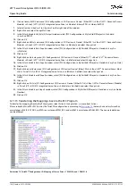
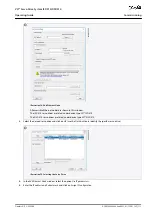
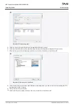
To set the communication parameters, double-click on the icon depicting the servo drive in the main window showing the
Ethernet network.
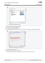
In the
General
tab, enter a name in field
Device name
.
In the
General
tab, click on the
Ethernet...
button to set the IP address of the servo drive and then click on
OK
.
Repeat steps 6–9 for:
Power Supply Module (PSM 510):
VLT PSM IRT
Decentral Access Module (DAM 510):
VLT DAM IRT
Auxiliary Capacitors Module (ACM 510):
VLT ACM IRT
6.13.6 Assigning IP Configuration and Device Name
N O T I C E
If more than 1 servo drive is used in the same PROFINET
®
network, each servo drive must have a different name and IP ad-
dress.
The IP address assignment is also required when using indirect communication via the VLT
®
Toolbox software (see the
VLT®
Servo Drive System ISD 510, DSD 510, MSD 510 (VLT® Flexmotion
™
) Programming Guide
for further information).
Procedure
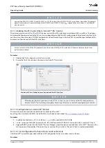
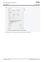
Open menu [PLC
→
Ethernet
→
Edit Ethernet Node].
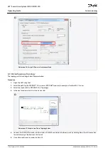
In the next window, click on
Browse
.
AQ262449648484en-000101 / 175R1135
110 | Danfoss A/S © 2020.08
Commissioning
VLT® Servo Drive System ISD 510/DSD 510
Operating Guide

