


External Interlock
is displayed, this indicates that
the unit is ready to operate but is missing an
input signal on terminal 27.
•
When factory installed optional equipment is
wired to terminal 27, do not remove that wiring.
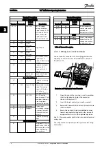
2.4.5.7 Terminal 53 and 54 Switches
•
Analog input terminals 53 and 54 can select
either voltage (0 to 10 V) or current (0/4-20 mA)
input signals
•
Remove power to the frequency converter before
changing switch positions
•
Set switches A53 and A54 to select the signal
type. U selects voltage, I selects current.
•
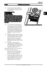
The switches are accessible when the LCP has
been removed (see
). Note that
some option cards available for the unit may
cover these switches and must be removed to
change switch settings. Always remove power to
the unit before removing option cards.
•
Terminal 53 default is for a speed reference signal
in open loop set in
16-61 Terminal 53 Switch
Setting
•
Terminal 54 default is for a feedback signal in
closed loop set in
16-63 Terminal 54 Switch Setting
130B
T310.10
1
2
N O
VLT
BUS TER.
OFF-ON
A53 A54
U- I U- I
Illustration 2.22 Location of Terminals 53 and 54 Switches
2.4.5.8 Terminal 37
Terminal 37 Safe Stop Function
The frequency converter is available with optional safe
stop functionality via control terminal 37. Safe stop
disables the control voltage of the power semiconductors
of the frequency converter output stage which in turn
prevents generating the voltage required to rotate the
motor. When the Safe Stop (T37) is activated, the
frequency converter issues an alarm, trips the unit, and
coasts the motor to a stop. Manual restart is required. The
safe stop function can be used for stopping the frequency
converter in emergency stop situations. In the normal
operating mode when safe stop is not required, use the
frequency converter’s regular stop function instead. When
automatic restart is used – the requirements according to
ISO 12100-2 paragraph 5.3.2.5 must be fulfilled.
Liability Conditions
It is the responsibility of the user to ensure personnel
installing and operating the Safe Stop function:
•
Read and understand the safety regulations
concerning health and safety/accident prevention
•
Understand the generic and safety guidelines
given in this description and the extended
description in the
Design Guide
•
Have a good knowledge of the generic and safety
standards applicable to the specific application
User is defined as: integrator, operator, servicing,
maintenance staff.
Standards
Use of safe stop on terminal 37 requires that the user
satisfies all provisions for safety including relevant laws,
regulations and guidelines. The optional safe stop function
complies with the following standards.
EN 954-1: 1996 Category 3
IEC 60204-1: 2005 category 0 – uncontrolled stop
IEC 61508: 1998 SIL2
IEC 61800-5-2: 2007 – safe torque off (STO)
function
IEC 62061: 2005 SIL CL2
ISO 13849-1: 2006 Category 3 PL d
ISO 14118: 2000 (EN 1037) – prevention of
unexpected start up
The information and instructions of the instruction manual
are not sufficient for a proper and safe use of the safe stop
functionality. The related information and instructions of
the relevant
Design Guide
must be followed.
Protective Measures
•
Safety engineering systems may only be installed
and commissioned by qualified and skilled
personnel
•
The unit must be installed in an IP54 cabinet or
in an equivalent environment
•
The cable between terminal 37 and the external
safety device must be short circuit protected
according to ISO 13849-2 table D.4
Installation
VLT
®
HVAC Drive Operating Instructions
20
MG11AH02 - VLT
®
is a registered Danfoss trademark
2
2


