VLT® 7000 Booster
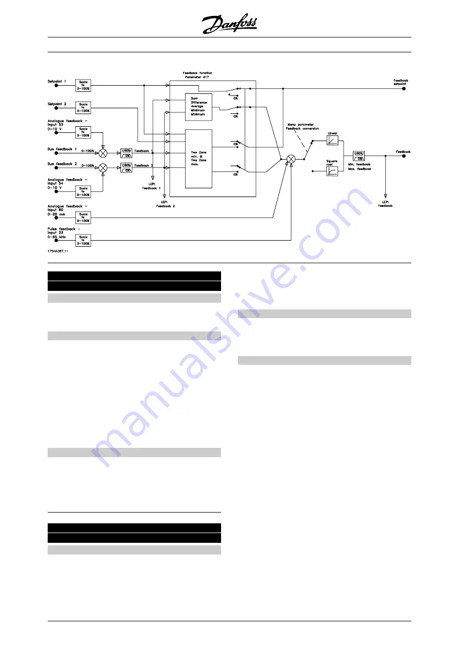
416 Feedback conversion
(FEEDBACK CONV.)
Value:
✭
Linear (LINEAR)
[0]
Square root (SQUARE ROOT)
[1]
Function:
In this parameter, a function is selected which
converts a connected feedback signal from the
process to a feedback value that equals the square
root of the connected signal.
This is used, e.g. where regulation of a flow (volume)
is required on the basis of pressure as feedback
signal (flow = constant x
√
pressure). This conversion
makes it possible to set the reference in such a
way that there is a linear connection between the
reference and the flow required.
Description of choice:
If
Linear
[0] is selected, the feedback signal and
the feedback value will be proportional.
If
Square root
[1] is selected, the frequency converter
translates the feedback signal to a square root value.
417 Feedback function
(2 FEEDBACK, CALC.)
Value:
Minimum (MINIMUM)
[0]
Maximum (MAXIMUM)
[1]
Sum (SUM)
[2]
Difference (DIFFERENCE)
[3]
Average (AVERAGE)
[4]
Feedback 1 only (FEEDBACK 1 ONLY)
[7]
Feedback 2 only (FEEDBACK 2 ONLY)
[8]
✭
Virtual Control Curve (VIRTUAL CTR CURVE)
[9]
Function:
This parameter allows a choice between
different calculation methods whenever two
feedback signals are used.
Description of choice:
If
Minimum
[0] is selected, the frequency converter will
compare
feedback 1
with
feedback 2
and regulate
on the basis of the lower feedback value.
Feedback 1
= Sum of parameter 535
Bus feedback 1
and the feedback signal value of terminal 53.
Feedback
2
= Sum of parameter 536
Bus feedback
2 and the
feedback signal value of terminal 54.
If
Maximum
[1] is selected, the frequency converter
will compare
feedback 1
with
feedback 2
and regulate
on the basis of the higher feedback value.
If
Sum
[2] is selected, the frequency converter will total
feedback 1
with
feedback 2
. Please note that the
remote reference will be added to
Setpoint 1
.
If
Difference [3
] is selected, the frequency converter
will subtract
feedback 1
from
feedback 2
.
If
Average
[4] is selected, the frequency converter
will calculate the average of
feedback 1
and
feedback 2
. Please note that the remote reference
will be added to the
Setpoint 1
.
If
Feedback 1 only
[7] is selected, terminal 53 is
read as the feedback signal and terminal 54 ignored.
Feedback 1 is compared to Setpoint 1 for drive control.
✭
= factory setting. () = display text [] = value for use in communication via serial communication port
MG.70.A1.02 - VLT is a registered Danfoss trademark
84