


1
Single, Double, T riple and Thru-drive Pumps Overhaul Service Manual V-PUVN-TS001-E October 2002
Section IV —
Installation and Operating
Instructions (cont.)
F. Overload Protection
Self pr iming: W ith a minimum
drive speed of 600 RPM, a
pump should prime
immediately. Failure to prime
within a short length of time
may result in damage due to
lack of lubrication. Inlet lines
must be tight and free from air
leaks. However, it may be
necessary to loosen a fitting on
the outlet side of the pump to
purge entrapped air.
No load star ting: These
pumps are designed to start up
with no load on the pressure
ports. They should never be
started against a load or a
closed center valve.
E. Hy draulic Fluid Recommendations (cont.)
Sound Lev el
Noise is indirectly af fected by
the fluid selection, but the
condition of the fluid is of
paramount importance in
obtaining optimum reduction
of system sound levels.
Some of the major factors
affecting fluid conditions that
cause the loudest noises in a
hydraulic system are:
1. Very high viscosities at start-
up temperatures can cause
pump noises due to cavitation.
2. Running with a moderately
high viscosity fluid will slow
the release of entrained air. The
fluid will not be completely
purged of such air in the time it
remains in the reservoir and air
will be recycled through the
system.
3. Aerated fluid can also be
caused by ingestion of air
through the pipe joints of inlet
lines, high velocity discharge
lines, cylinder rod packings, or
by fluid discharging above the
fluid level in the reservoir. Air in
the fluid causes a noise similar
to cavitation.
4. Contaminated fluids can
cause excessive wear of
internal pump parts, which
may result in increased
sound levels.
Relief valves must be installed
in the system as close to the
pump outlets as possible. The
relief valve limits pressure in
each system to a prescribed
maximum and protects
components from excessive
pressure. Each relief valve
pressure setting depends on
the work requirements of the
circuit being fed.
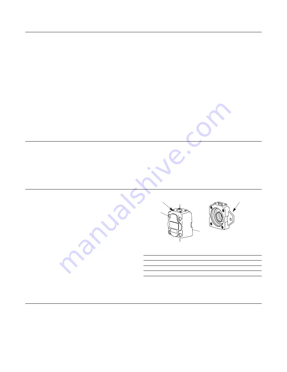
G. P ort Positions
H. Start-Up
The pump cover can be
assembled in four positions
with respect to the body.
A letter in the model code
identifies the orientation of the
inlet and outlet ports. The cover
position of a VMQ single pump
is shown in Figure 8 as an
example.
I
nlet Cover Positions
Model
(Viewed from cover end)
t
r
o
P
t
e
lt
u
O
e
ti
s
o
p
p
O
0
3
0
*
*
A
*
*
1
Q
M
V
0
9
0
3
0
*
*
B
*
*
1
Q
M
V
°Clockwise from Outlet
VMQ1* *C* * 030
Inline with Outlet
VMQ1* *D* * 030
90° Counterclockwise from Outlet
Figure 8.
Cover Positions
Disassembly and assembly procedures are in Section
VI-B and E.
Whenever it is possible to do
so, fill the pump ports with
system hydraulic fluid. This
will make it easier for the
pump to prime when it is first
started.
Body (Outlet)
Cover (Inlet)
A
B
C
D
Summary of Contents for Vickers VMQ125S
Page 22: ......


