Danfoss Vacon NXP Design Manual Download Page 13


5 Installation Guidelines

5.1 Cabling

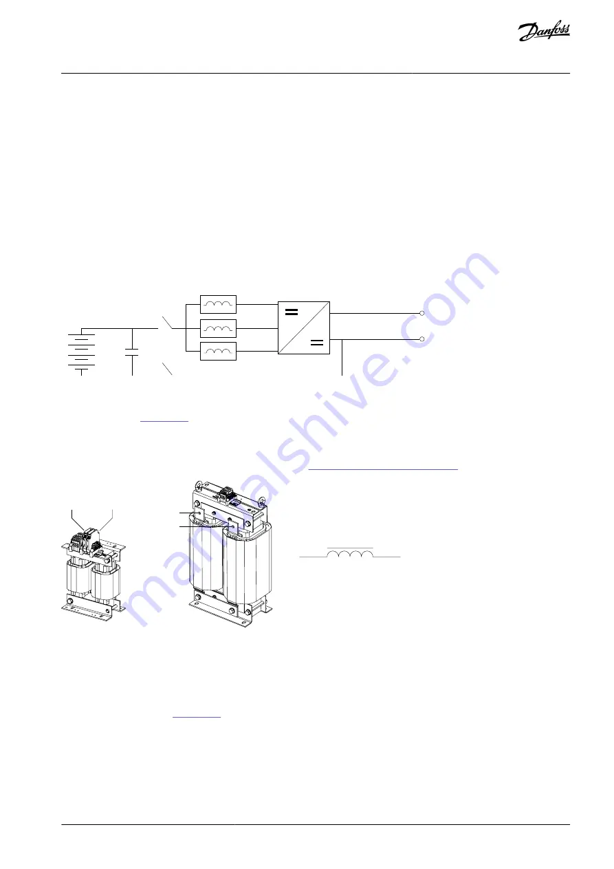
The DC filter is connected between the DC/DC converter and the DC source. Three L-type inductors are required for a typical DC/DC
converter application. The order code for the listed L-type DC filters includes three 1-phase inductors.
For EMI reasons, keep the cable length between the DC source and DC/DC converter as short as possible. Sometimes, the parasitic
components of the source and cable can resonate with the DC filter inductors, causing instability in the control. The resonance can
be avoided by adding an external filtering capacitor (C) to the output of the DC filter. The formed LC filter resonance must be well
below the switching frequency.
To reduce the radiation of electromagnetic noise into the environment and to prevent malfunctions in the installation, use shielded
cables.
If unshielded cables are used, make sure that the installation minimizes the possibility of cross-coupling with other cables that are
carrying sensitive signals. This can be achieved, for example, by cable routing.
Follow the instructions for cable size selection for the DC/DC converter.

DC Source

DC/DC Converter

DC link

DC+

DC-

L

C

e3

0b

j3

52

.1

0

Illustration 2: DC Filter Connections

The L-type inductors have two winding poles connected in series. The terminals are at the top of the 1-phase inductors, and are
marked as shown in 

Illustration 3

.

10–30 A inductors have terminal connectors.
50–1150 A inductors have busbar terminals.

DC filter terminal sizes and mounting specifications are given in 

7.6 Terminal and Torque Specifications

.

L

in

/L

out

L

in

/L

out

L

in

L

out

L

out

/L

in

L

out

/L

in

e3

0b

j4

95

.1

0

Illustration 3: DC Filter Terminals

5.2 Thermal Protection

Depending on requirements, the DC filter can be selected with built-in Pt100 temperature sensors or thermal relays (normal closed).
If temperature level monitoring is required, select the Pt100 type DC filter. The thermal relay type protection is used for indication of
alarm and fault limits of the DC filter. The temperature sensors are mounted in all three separate inductors. The wiring of the tem-
perature sensors is shown in 

Illustration 4

.

The option board OPT-BH is required for the Pt100 sensors. Each sensor is wired to its own channel. Thermal relay type sensors can
be connected to any digital input of the drive. One digital input is used for the alarm signal and another for the fault signal by wiring
the sensors in series. The auxiliary power input is the same for both the alarm and fault sensors.
Switching temperatures of the thermal relays depend on the DC filter type. See the datasheet of the DC filter for specific values. The
temperature limits are:

Alarm = 125–140 °C
Fault = 140–155 °C

AJ377845348678en-000101 / 172F4785 | 13

Danfoss A/S © 2023.01

Installation Guidelines

DC Filters

Design Guide

Summary of Contents for Vacon NXP

Page 1: ...Design Guide DC Filters VACON NXP DC DC Converter drives danfoss com...

Page 2: ......

Page 3: ...ing 7 DC Filter Types 7 Selection 9 Selecting the DC Filter 9 DC Filter Selection Air cooling 9 DC Filter Selection Liquid cooling 11 Installation Guidelines 13 Cabling 13 Thermal Protection 13 Mounti...

Page 4: ...nd options The VACON NXP DC DC Converter operating guide provides information about the installation and operation of the VACON NXP DC DC Converter application The VACON NXP DC DC Converter applicatio...

Page 5: ...dous situation which if not avoided will result in death or serious injury W A R N I N G Indicates a hazardous situation which if not avoided could result in death or serious injury C A U T I O N Indi...

Page 6: ...for lifting purposes C A U T I O N BURN HAZARD FROM HOT SURFACES The filter surface turns hot during operation Wait for the filter to cool down before touching it N O T I C E DAMAGE FROM LOOSE CONNEC...

Page 7: ...be as high as 1100 V that is 1150 V D input and 50 V DC output Due to the high voltage difference a high inductance value is required to guarantee proper functionality in all operation points The DC f...

Page 8: ...tion rating 0 IP00 2 IP21 5 IP54 A Cooling method A Natural convection B Forced air cooling C Liquid cooling Pt Temperature measurement type Pt Pt100 temperature sensor Tr Thermal relay X Reserved for...

Page 9: ...age max current fs 5 kHz Iout nominal A Filter selection Iout max A Filter selection FR4 NXI_0004 5 4 8 LDC 0010 6 0 Axx 8 LDC 0010 6 0 Axx NXI_0009 5 10 18 NXI_0012 5 13 4 24 FR6 NXI_0016 18 LDC 0010...

Page 10: ...DC fs 5 kHz Low Voltage max current fs 5 kHz Iout nominal A Filter selection Iout max A Filter selection FR6 NXI_0010 6 11 1 LDC 0010 6 0 Axx 14 6 LDC 0010 6 0 Axx NXI_0013 6 14 6 19 NXI_0018 6 20 3...

Page 11: ...ble 5 DC Filter Selection for Liquid cooled 500 V Drives According to Energy Storage Requirements Drive enclosure size Drive type High Voltage 750 V DC fs 5 kHz Low Voltage max current fs 5 kHz Iout n...

Page 12: ...ut nominal A Filter selection Iout max A Filter selection CH61 NXP_0170 6 199 LDC 0160 6 0 Cxx 340 LDC 0160 6 0 Cxx NXP_0208 6 244 416 NXP_0261 6 309 500 CH62 NXP_0325 6 385 650 LDC 0340 6 0 Cxx NXP_0...

Page 13: ...re at the top of the 1 phase inductors and are marked as shown in Illustration 3 10 30 A inductors have terminal connectors 50 1150 A inductors have busbar terminals DC filter terminal sizes and mount...

Page 14: ...lt signal connected to terminals 3 and 4 1 2 3 4 e30bj645 10 Illustration 5 Terminals for Thermal Protection 5 3 Mounting The DC filter is typically mounted inside a cabinet next to the DC DC converte...

Page 15: ...ra air baffles and fan In the filter range above 50 A the cooling arrangement must be implemented The cabinet cooling must be guaranteed also with liquid cooled DC filters Typically 30 40 of the power...

Page 16: ...of the cabinet with care Do not use liquids for the cleaning Tightening torques Check that the tightening torques of the cable connections are according to the specifications See 7 6 Terminal and Torq...

Page 17: ...2 Environmental Data Table 8 Environmental Data for the DC Filters Item Specification Temperature during operation 10 50 C full performance 50 60 C limited performance Current derating of 2 for each...

Page 18: ...ctions Following the drive system connections Cooling system materials Stainless steel AISI304 AISI316 Aluminum Corrosion resistant Glycol tolerant plastics Not allowed Copper brass PVC 7 4 Technical...

Page 19: ...LDC 0170 6 0 APt 37404 SET PT100 1025 AN 170 450 IP00 5 181B5971 LDC 0170 6 0 ATr 37404 SET THER MIK 181B5972 LDC 0270 5 0 APt 38739 SET PT100 750 AN 270 460 IP00 5 181B5973 LDC 0270 5 0 ATr 38739 SE...

Page 20: ...1150 6 0 CTr 36859 SET THERMIK 7 5 Dimensions The dimensions in Table 13 refer to drawings shown in Illustration 7 Illustration 8 and Illustration 9 Details of the terminal connec tions can be found...

Page 21: ...C 0420 5 0 APt 308 10 273 10 587 7 252 198 220 11x21 130 LDC 0420 5 0 APt LDC 0540 6 0 BPt 306 10 287 7 560 7 252 198 220 11x21 123 LDC 0540 6 0 BTr LDC 0900 5 0 BPt 276 10 240 5 484 5 186 210 150 11x...

Page 22: ...tion 7 Dimensions of the Air cooled Inductors 10 30 A A E B D F G C e30bj350 10 Illustration 8 Dimensions of the Air cooled Inductors 30 A AJ377845348678en 000101 172F4785 22 Danfoss A S 2023 01 Speci...

Page 23: ...LDC 0092 5 0 Axx Busbar 1 x D9 M8 M8 20 20 Base LDC 0092 6 0 Axx Busbar 1 x D9 M8 M8 20 20 Base LDC 0092 5 0 Bxx Busbar 1 x D9 M8 M8 20 20 Base LDC 0170 6 0 Axx Busbar 1 x D11 M10 M10 40 40 Base LDC...

Page 24: ...l Grounding Terminal Grounding LDC 0340 6 0 Cxx Busbar D 13x20 M12 M10 70 40 Base LDC 0700 6 0 Cxx Busbar D 13x20 M12 M10 70 40 Base LDC 1150 6 0 Cxx Busbar D 13x20 M12 M10 70 40 Base AJ377845348678en...

Page 25: ...lter types 7 L Liquid cooling 18 M Maintenance 16 Mounting 14 O Overview 7 P Purpose of the manual 4 R Recycling 16 S Safety 5 Selection 9 Specifications 17 Symbols 5 T Technical data 18 Terminals 23...

Page 26: ...ures and other printed material Danfoss reserves the right to alter its products without notice This also applies to products already on order provided that such alterations can be made without subseq...

Reviews: