background image

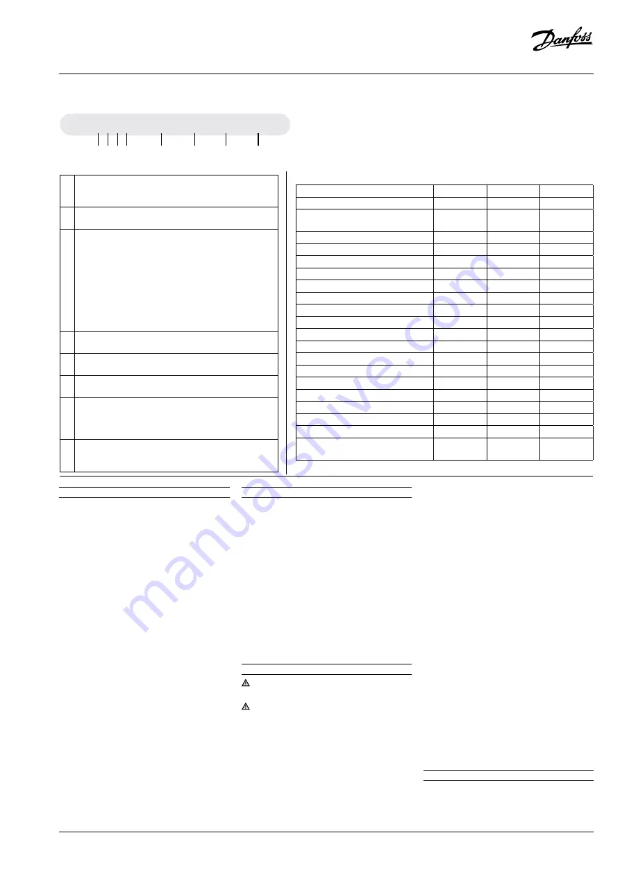
  OP - MPXM    034    ML     P00    G

1 2 3 4

5

6

7

8

1 Application


M = MBP 
L = LBP

2 Package


Condensing unit family: P = Optyma™ Plus

3 Refrigerant


H = R404A/R507
G = R134a, R513A 
Q = R452A, R404A/R507
X =  R404A/R507, R134a, R407A, R407F, R448A, R513A 

R449A,R452A

Y = R404A/R507, R449A 
B =  R448A/R449A/R404A/R452A (MBP)  
P = R448A/R449A, R407A/F, R404A/R507 
O = R448A/R449A/R404A/R452A (LBP)

4 Condenser


M = Microchannel heat condenser

5 Swept volume


Displacement in cm

3: 

Example 034 = 34 cm

3

6 Compressor platform


ML= Fixed speed scroll MLZ

7 Version 

P00: Optyma™ Plus 
P02: Optyma™ Plus with Liquid Injection
P05: Optyma™ Plus with Supply monitoring relay

8 Voltage code 

G = 230V/1-phase/50Hz compressor & fan
E = 400V/3-phase/50Hz compressor & 230V/1-phase fan

Optyma™ 

Plus

(P00)

(P02)

(P05)

IP level

IP54

IP54

IP54

Compressor technology

Scroll/

Reciprocating

Scroll

Scroll (3phase)

Control box (pre-wired E-panel)

yes

yes

yes

Microchannel condenser

yes

yes

yes

Fan speed controller*

yes

yes

yes

Main switch (circuit breaker)

yes

yes

yes

Supply monitoring relay

-

-

yes

Filter drier (flare connections)

yes

yes

yes

Sight glass

yes

yes

yes

Crankcase heater

yes

yes

yes

HP/LP adjustable pressostat

Electronic

Electronic

Electronic

Fail safe mini-pressostat

Mechanical

Mechanical

Mechanical

Access door(s)

yes

yes

yes

Acoustic insulation

yes

yes

yes

Condensing unit electronic controller

yes

yes

yes

Network connectivity

yes

yes

yes

Stack mounting

yes

yes

yes

Discharge gas thermostat

yes

yes

yes

HP/LP Alarm

yes

yes

yes

Liquid injection kit, phase loss/
sequence protection

-

yes

-

Version control

Designation system for the 

Optyma

™ Plus range

* Inbuilt function within Condensing unit electronic controller

Instructions

118U3276G - AN18658643414604-001701 | 3

© Danfoss | Climate Solutions | 2022.02

1 – Introduction

These instructions pertain to Opty-
ma

 Plus condensing units OP-MPYM, 


OP-MPXM, OP-MPGM, OP-LPQM, OP-LPOM & OP-
MPBM used for refrigeration systems. They pro-
vide necessary information regarding safety and 
proper usage of this product.

The condensing unit includes following:
  •    Microchannel  heat  exchanger
  •   Reciprocating or scroll compressor
  •  Receiver with stop valve
  •   Ball  valves
  •   Sight  glass
  •  High & low pressure switches
  • Replaceable filter drier
  •   Electronic  controller
  •  Main circuit breaker (Main switch with overload 

protection)

  •  Fan and compressor capacitors
  •   Compressor  contactor
  •    Supply  monitoring  relay**
  •  Robust weather proof housing
  •  Liquid injection controller (Module B Plus)*
  •  Electronic expansion valve (ETS6)*

*Only for P02 version, 
**only for P05 models 

2 – Handling and storage

 •  It is recommended not to open the packaging 

before the unit is at the final place for installa-
tion.

 •  Handle the unit with care. The packaging al-

lows for the use of a forklift or pallet jack. Use 
appropriate and safe lifting equipment..

  •  Store and transport the unit in an upright posi-

tion.

  •  Store the unit between -35°C and 50°C.
  •  Don’t expose the packaging to rain or corrosive 

atmosphere.

 •  After unpacking, check that the unit is com-

plete and undamaged.

3 – Installation precautions

 Never place the unit in a flammable atmos-

phere.

 Place the unit in such a way that it is not bloc-

king or hindering walking areas, doors, windows 
or similar.

 •  Ensure adequate space around the unit for air 

circulation and to open doors. Refer to picture 
1 for minimal values of distance to walls.

 •  Avoid installing the unit in locations which are 

daily exposed to direct sunshine for longer pe-
riods.

  •  Avoid installing the unit in aggressive and dus-

ty environments.

 •  Ensure a foundation with horizontal surface 

(less than 3° slope), strong and stable enough 
to carry the entire unit weight and to eliminate 
vibrations and interference. 

  •  The unit ambient temperature may not exceed 

50°C during off-cycle.

 •  Ensure that the power supply corresponds to 

the unit characteristics (see nameplate).

 •  When installing units for HFC refrigerants, use 

equipment specifically reserved for HFC refri-
gerants which was never used for CFC or HCFC 
refrigerants.

 •  Use clean and dehydrated refrigeration-grade 

copper tubes and silver alloy brazing material.

  •  Use clean and dehydrated system components.
 •  The suction piping connected to the compres-

sor must be flexible in 3 dimensions to dampen 
vibrations. Furthermore piping has to be done 
in such a way that oil return for the compres-
sor is ensured and the risk of liquid slug over in 
compressor is eliminated.

4 – Installation

 •  The installation in which the condensing unit is 

installed must comply to pressure Equipment 
Directive (PED) 2014/68/EU. The condensing unit 

Summary of Contents for Optyma Plus

Page 1: ...h p 56 E Greek p 62 Norsk Norwegian p 68 B lgarski Bulgarian p 74 Rom n Romanian p 80 e tina Czech p 86 Polski Polish p 92 Russian p 98 GA Drawings GA tegninger GA Zeichnungen Sch mas GA Diagramas GA...

Page 2: ...4X41 250 550 456 456 Housing 2 Code n 114X32 or 114X42 250 650 530 530 Housing 3 Code n 114X33 or 114X43 250 760 581 581 Housing 4 Code n 114X34 or 114X44 250 900 700 700 Picture 1 Minimum mounting di...

Page 3: ...switches Replaceable filter drier Electronic controller Main circuit breaker Main switch with overload protection Fan and compressor capacitors Compressor contactor Supply monitoring relay Robust wea...

Page 4: ...are also equipped with phase sequence relay to protect the unit against phase loss sequence asymmetry and under over voltage For units with a 3 phase scroll compressor OP MPXMxxxxxxxxE correct phase s...

Page 5: ...nspections 14 Emergency running without controller In case of controller failure the condensing unit can still be operated when the controller standard wiring picture 4 is modified into a temporary wi...

Page 6: ...testing and test methods part 2 Condensing units 17 Warranty Always transmit the model number and serial number with any claim filed regarding this pro duct The product warranty may be void in followi...

Page 7: ...interface Module B Plus powers on power LED 1 will be solid red all the time When the Module is powered off power LED 1 will be off If Module B Plus powers on and has no error status LED 2 will be so...

Page 8: ...k Tryk p den nederste knap for at skifte til tempe raturv rdien for kondenseringstrykket Billede 3 Elektronisk regulatordisplay W Q R X Z Y Q Luft ind R Luft ud Enhed W mm X mm Y mm Z mm Hus 1 Kodenr...

Page 9: ...ter Elektronisk regulator Hovedafbryder hovedafbryder med overbe lastningssikring Ventilator og kompressorkondensatorer Kompressorkontaktor Forsyningsoverv gningsrel Robust vejrbestandigt hus V skeind...

Page 10: ...mpres sorens omdrejningsretning p aggregater med en 3 faset scroll kompressor OP MPXMxxxxxxxxE Find faser kkef lgen ved hj lp af en fasem ler for at etablere faser kkef lgen for fase L1 L2 og L3 Tilsl...

Page 11: ...og t thed kontrolleres Not r b de k lemiddeltypen og fyldningen foruden driftsbetingelserne Dette anvendes som referencepunkt ved fremtidige eftersyn 14 N ddrift uden regulator Kondenseringsaggregatet...

Page 12: ...g v skek lere til pro cesk ling Kondenseringsaggregatm linger er udf rt i henhold til standarden EN 13771 2 2017 Kom pressorer og kondenserende enheder til k ling Ydeevnepr vning og pr vningsmetoder D...

Page 13: ...r slukket vil LED 1 v re slukket Hvis Modul B Plus t nder og ikke har nogen fejl vil LED 2 v re konstant gr n Se billede 6 vedr rende placering af LED 1 og LED 2 p Modul B Plus Hvis Modul B Plus t nde...

Page 14: ...017 OP MPYM008 009 012 014 OP MPHM007 010 012 015 018 H1 OP LPQM026 048 068 074 OP MPBM018 024 026 034 OP MPXM034 046 057 OP MPGM033 34 OP MPHM026 034 OP LPHM026 H2 Instructions 104 AN18658643414604 0...

Page 15: ...on are in mm Dansk Legend A 12 hul til montering B Skueglas C Regulatordisplay D Luft ind E Luft ud F Suger r G V sker r H Typeskilt Elektriske ledninger Bem rk Alle m l angives i mm Deutsch Legende A...

Page 16: ...ning voor de bevestiging B Kijkglas C Regelaar display D Luchtinlaat E Luchtuitlaat F Zuigpoort G Vloeistofpoort H Typeplaatje Elektrische kabels Opmerking alle afmetingen zijn in mm Suomi Legenda A 1...

Page 17: ...dge Switch auto reset PSL R1 Ambient Temperature sensor T4 R2 Discharge Temperature Sensor T2 R3 Suction Temperature Sensor T3 R8 Discharge Temperature Sensor T1 Insulation P00 Models OP LPQM017 026 0...

Page 18: ...s 7 Fl ssigkeits Kugelabsperrventil 8 Saugseitiges Kugelabsperrventil B1 Druckmessaufnehmer Hochdruck P1 B2 Druckmessaufnehmer Niederdruck P2 B3 Hochdruck Patronendruckschalter automa tisches Zur ckse...

Page 19: ...presostat automatick reset PSL R1 Sn ma teploty okol T4 R2 Sn ma v tla n teploty T2 R3 Sn ma sac teploty T3 R8 Sn ma v tla n teploty T1 Izolace Polski Legenda 1 Spr arka 2 Elektryczny zaw r rozpr ny 3...

Page 20: ...Code G OP LPQM048 068 WD 1 Instructions 110 AN18658643414604 001701 118U3276G Danfoss Climate Solutions 2022 02...

Page 21: ...Code G OP LPQM026 074 OP MPGM033 OP LPHM018 OP MPBM018 024 026 034 WD 2 Instructions 118U3276G AN18658643414604 001701 111 Danfoss Climate Solutions 2022 02...

Page 22: ...Code G OP MPXM068 080 Instructions 112 AN18658643414604 001701 118U3276G Danfoss Climate Solutions 2022 02 WD 3...

Page 23: ...Code E OP MPBM026 034 Instructions 118U3276G AN18658643414604 001701 113 Danfoss Climate Solutions 2022 02 WD 4...

Page 24: ...Code E OP LPQM048 068 074 OP MPXM034 046 057 Instructions 114 AN18658643414604 001701 118U3276G Danfoss Climate Solutions 2022 02 WD 5...

Page 25: ...Code E OP LPOM067 084 098 Instructions 118U3276G AN18658643414604 001701 115 Danfoss Climate Solutions 2022 02 WD 6...

Page 26: ...Instructions 116 AN18658643414604 001701 118U3276G Danfoss Climate Solutions 2022 02 Code E OP LPOM120 168 WD 7...

Page 27: ...Code G OP LPQM017 OP MPYM008 009 012 014 Instructions 118U3276G AN18658643414604 001701 117 Danfoss Climate Solutions 2022 02 WD 8...

Page 28: ...Instructions 118 AN18658643414604 001701 118U3276G Danfoss Climate Solutions 2022 02 Code G OP MPXM034 046 057 WD 9...

Page 29: ...Instructions 118U3276G AN18658643414604 001701 119 Danfoss Climate Solutions 2022 02 Code E OP LPQM215 271 OP MPXM125 162 WD 10...

Page 30: ...Instructions 120 AN18658643414604 001701 118U3276G Danfoss Climate Solutions 2022 02 Code E OP LPQM096 136 OP MPXM068 080 108 WD 11...

Page 31: ...Instructions 118U3276G AN18658643414604 001701 121 Danfoss Climate Solutions 2022 02 Code E P05 OP MPXM034 046 057 WD 12...

Page 32: ...Instructions 122 AN18658643414604 001701 118U3276G Danfoss Climate Solutions 2022 02 Code E P05 OP MPXM068 080 108 WD 13...

Page 33: ...Instructions 118U3276G AN18658643414604 001701 123 Danfoss Climate Solutions 2022 02 Code E P05 OP MPXM125 162 WD 14...

Page 34: ...ar g B4 Pressostato bassa pressione OFF 0 3bar g ON 0 5bar g C1 Condensatore di avviamento compressore C2 Condensatore di marcia compressore C3 Condensatore di marcia ventola 1 C4 Condensatore di marc...

Page 35: ...otorbeveiliging K1 Schakelaar K2 Startrelais M1 Compressor M2 Ventilatormotor 1 M3 Ventilatormotor 2 M4 Elektronisch expansieventiel Q1 Hoofdschakelaar R1 Sensor omgevingstemperatuur R2 R8 Voeler pers...

Page 36: ...e a motorului K1 Contactor K2 Releu de pornire M1 Compresor M2 Motor ventilator 1 M3 Motor ventilator 2 M4 Valv electronic de expansiune Q1 Comutator principal R1 Senzor temp ambiant R2 R8 Senzor temp...

Reviews: