


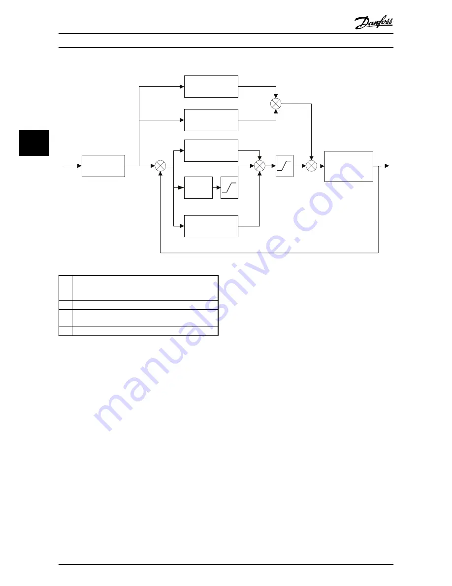
Motor and
FC300
FFVEL
FFACC
KDER
Setpoint
generator
Position
Reference
CA
CV
CP
AP
KPROP
KINT
KILIM
BANDWIDTH
+
+
+
+
+
+
–
–
130BB809.
10
AP
is the actual position (calculated from encoder feedback) in
qc (Quad Counts)
CP
is the current position set point in qc
CV
is the velocity set point in qc/ms (position deviation) is
calculated by CP-AP
CA
is the acceleration set point
The PID filter works according to the following formula:
1 = FFVEL * (Setpoint Velocity)
2 = FFACC * (Setpoint Acceleration)
3 = KPROP * (Position Deviation)
4 = KINT * (Sum of all previous Position Deviations)
(limited by KILIM)
5 = KDER * (Difference of Position Deviation)
6 = 3 + 4 + 5 (Limited by BANDWIDTH)
NOTE
In SYNCV mode the PID controller is working with speed
deviation instead of position deviation. Speed deviation is
calculated by CV–AV. (AV is the Actual Velocity)
The controller in the MCO 305 utilizes two control
strategies at the same time:
1.
An open-loop feed-forward control. Since the
asynchronous motor inherently has a good open
loop performance the feed-forward control is a
very important part of the controller in most
applications. Benefits from using feed-forwards
control is a very fast and accurate response to
changes in the
setpoint reference
.
2.
A closed-loop PID control. The PID controller
monitors the difference between the actual
position and the setpoint position. Based on this
information it calculates a control signal to
minimize the position deviance. Thus the MCO is
able to compensate for changes in load or
friction. The PID controller is also necessary to
compensate for any position deviance caused by
inaccurate setting of the open-loop feedforward
controller.
In short: The feed-forward control is used to handle
changes in the setpoint reference (especially important in
synchronization applications), while the PID control is used
to handle changes in load conditions or inaccuracies of the
feed-forward control.
4.3 PID Factors
The
32-60 Proportional factor
is multiplied with the position
deviance and the result is added to the control signal (the
internal speed-reference to the VLT AutomationDrive).
Since the calculated control signal is proportional to the
position deviance (or error) this kind of control is called
proportional control. The behavior of the proportional
control is similar to that of a spring – the further the
spring is extended the stronger the counter-force it
produces.
Optimizing the PID controll...
MCO 305 Operating Instructions
20
MG.33.K3.02 - VLT
®
is a registered Danfoss trademark
4
4