MAKING MODERN LIVING POSSIBLE
Technical Information
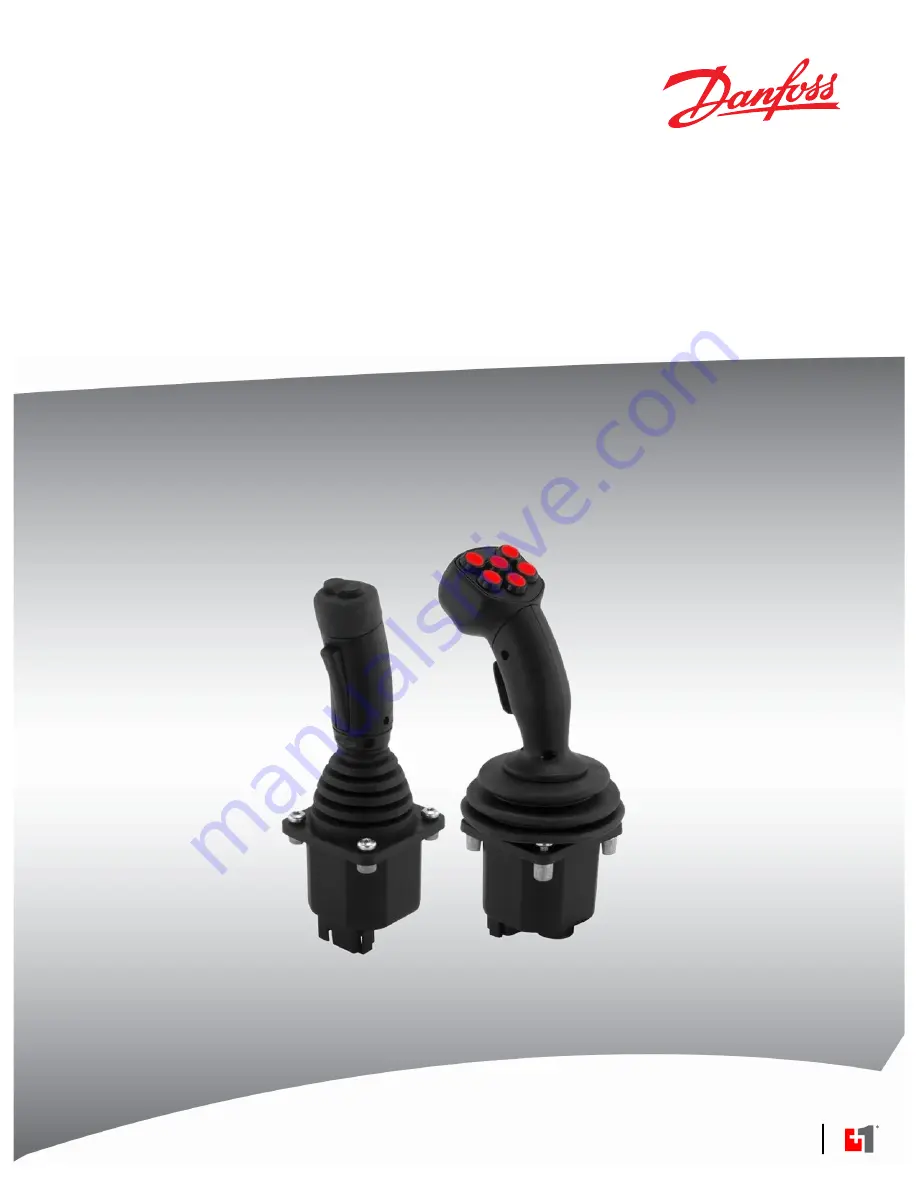
Joysticks
JS6000 Joystick Base
powersolutions.danfoss.com
Page 1: ...MAKING MODERN LIVING POSSIBLE Technical Information Joysticks JS6000 Joystick Base powersolutions danfoss com...
Page 2: ...late Diagram illustration Environmental Characteristics JA September 2009 Content update IA January 2008 A grip front plate diagram updated HA November 2007 Grip options model code details mechanical...
Page 3: ...oystick location CAN source address 19 H4 CAN proportional output 20 Code I J K L Grip options 20 JS6000 CAN messages CAN option 21 CAN option 21 CAN external inputs 21 Analog inputs AIN 21 Digital in...
Page 4: ...AN output mating connector DEUTSCH DTM06 6S 35 CAN and PWM output connector pin assignments 36 CAN and PWM output mating connector DEUTSCH DT16 18SB 37 Potentiometer sensor with analog output connecto...
Page 5: ...erating parameters e g ramp rates button function assignments output characteristics to be configured using the PLUS 1 Service Tool interface Refer to JS6000 PWM User Manual 11060942 for instructions...
Page 6: ...tick base and joystick grip information JS6000 Joystick Base Technical Information Manual 520L0760 provides information required to configure the base portion of the joystick JS1000 JS6000 Joystick Gr...
Page 7: ...axis Vo 25 to 75 of Vs 5 neutral threshold PUU Potentiometer dual output per axis Vo 10 to 90 of Vs 1 5 neutral threshold HMM Hall effect dual sensors per axis Vs 5 VDC Vo 0 5 to 4 5 VDC CAN Hall eff...
Page 8: ...n held in Y axis no X axis center detent 1 25 Nm 0 92 lb ft friction hold force 3 25 Nm 2 40 lb ft breakout force HC Friction held in Y axis no X axis center detent 2 25 Nm 1 66 lb ft friction hold fo...
Page 9: ...og outputs when H1 S 33 Source address 0x 33 use this source address with PWM outputs 34 Source address 0x 34 35 Source address 0x 35 36 Source address 0x 36 Consult the factory if additional source a...
Page 10: ...umber of operational axes Single Axis Base NY with friction hold option in the configuration code Y Axis Y Axis Dual Axis Base XY in the configuration code Y Axis Orientation Mark lift boot X Axis Y A...
Page 11: ...X and Y Operation or movement 20 0 20 0 20 0 20 0 20 0 20 0 20 0 20 0 P200 001 Technical Information JS6000 Joystick Base Model code details 520L0760 Rev 1102 November 2015 11...
Page 12: ...communication 18 pin connector PWM Hall effect dual sensors per axis Vs 9 to 36 VDC high current PWM and digital outputs See H1 electrical interface options on page 19 Potentiometer sensor The potenti...
Page 13: ...t Voltage Vs Switch track angle Resistance k Order code 10 2 90 2 1 5 1 6 to 2 4 R 25 2 75 2 1 5 2 2 to 3 6 Q 10 2 90 2 5 1 6 to 2 4 S 25 2 75 2 5 2 2 to 3 6 T W Warning Potential uncommanded machine...
Page 14: ...t voltage 90 4 Vs Controller Area Network CAN output Three versions of JS6000 CAN joysticks are available A grip MG grip HKN grip CAN configuration model code CAN CAN 2 0bB J1939 protocol and CANopen...
Page 15: ...ion range of the system and determine whether any resonance exists in the joystick Resonance causes dither and could cause the joystick to leave neutral Centering spring selection Spring option Breako...
Page 16: ...ls of friction breakout from center force are available Friction hold selection Friction hold torque Center detent breakout torque Order code No mechanical options NL 1 25 Nm 0 92 lbft 2 50 Nm 1 84 lb...
Page 17: ...21 20 19 18 1716 15 14 13 12 11 10 2459 Torque N m JS6000 HC option Angle 3 0 2 5 4 5 4 5 4 0 4 0 5 0 5 0 3 5 2 0 1 5 1 0 0 5 0 0 0 5 1 0 1 5 2 0 2 5 3 0 3 5 1 0 2 3 4 5 6 7 8 9 9 8 7 6 5 4 3 2 1 10...
Page 18: ...to center mechanical operation Optional microswitches are not available on BMM CAN CPL or PWM output joysticks The Honeywell microswitch electrical details follow These details are taken directly fro...
Page 19: ...information in 2 0B J1039 message protocol CANopen 2 0B J1939 protocol The CANopen output option provides conditioned joystick output information in 2 0B CANopen message protocol PWM The PWM output op...
Page 20: ...Analog or PWM 1 CAN full scale output 1000 counts Code I J K L Grip options JS6000 product configuration model code I I J K L M N O P Q R S J S 6 0 0 0 X Y H M M H S N L N W 3 3 1 A 0 H 0 R V N N N N...
Page 21: ...m external inputs External analog data is scaled in raw form from 0 to 1000 counts Data associated with CAN pins 9 10 11 and 12 is broadcast in both Basic Joystick Message 3 and Extended Joystick Mess...
Page 22: ...following Warning statement Button 11 W Warning Potential uncommanded machine movement JS6000 CAN Joysticks fitted with an operator present switch have an internal connection between the operator pre...
Page 23: ...e data field contains the joystick s output information SAE J1939 data fields contain 8 bytes of data Information in the data field Byte 0 1 2 and so on Bit 1 2 3 4 5 6 7 8 1 2 3 4 5 6 7 8 1 2 3 4 5 6...
Page 24: ...proportional input definitions Data field examples Byte 0 Bit 8 7 6 5 4 3 2 1 The 2 LSB of X axis position X axis lever right positive status X axis lever left negative position status X axis neutral...
Page 25: ...interface options section of the master model code The master model code specifies that the full scale output at the end of each linear zone will be 1000 counts W Warning Potential uncommanded machine...
Page 26: ...ter model code specifies that the full scale output at the end of each linear zone will be 1000 counts W Warning Potential uncommanded machine movement Per the SAE J1939 71 standard if the JS6000 joys...
Page 27: ...s 0 5 2 Grip X axis lever right positive position status 0 7 through 1 1 8 10 Grip X axis position 2 1 2 Grip Y axis neutral position status 2 3 2 Grip Y axis lever back negative position 2 5 2 Grip Y...
Page 28: ...ta 2664 4 Failure Input not calibrated Message Axis SPN FMI BJM1 X 2660 13 BJM1 Y 2661 13 BJM1 Grip X 2662 13 BJM1 Grip Y 2663 13 BJM1 Grip Theta 2664 13 Failure Redundant input failure Message Axis S...
Page 29: ...cks and click on CANopen EDS to open CANopen Object Dictionary A grip button and rocker CAN naming conventions A grip front plate diagram 2247B A2H0 A2HD A300 A30T A30D A30B A400 A40T A40D A40B 2 3 X...
Page 30: ...Joystick Message 1 EJM1 using the X and Y axis data bits See A grip button and rocker CAN naming conventions on page 29 for proportional rocker output X and Y naming conventions Each rocker switch al...
Page 31: ...on 1 Switch 2 Position CAN Grip Button 2 Switch 1 Position CAN Grip Button 1 Operator Present Switch CAN Grip Button 8 Operator Present Switch CAN Grip Button 8 Operator Present Switch CAN Grip Button...
Page 32: ...101 6 04 0 maximum 165 6 496 maximum 3 218 3 2 0 12669 0 126 typical 11 93 12 00 0 46968 0 4724 9 518 9 531 0 37472 0 37523 32 0 1 26 15 0 0 59 9 7 0 382 The JS6000 is designed to be installed from th...
Page 33: ...ternators or fuel pumps from sensor and other noise sensitive input wires Run wires along the inside of or close to metal machine surfaces where possible this simulates a shield which will minimize th...
Page 34: ...ty or are no longer received PWM joystick outputs will return to zero output if the joystick s embedded microcontroller detects a measurement error between the redundant shaft position sensors Applica...
Page 35: ...mating connector kits bag assemblies for JS6000 joysticks The bag assembly contains loose parts you must assemble The connector with wire harness features a fully assembled connector with an untermina...
Page 36: ...7 Sensor ground 8 5 Vdc sensor power 9 AIN1 DIN7 10 AIN2 DIN8 11 AIN3 DIN9 12 AIN4 DIN10 13 DIN1 14 DIN2 15 DIN3 16 DIN4 17 DIN5 18 DIN6 PWM output connector pinout and wiring information Pin CAN out...
Page 37: ...resence CAN and PWM output mating connector DEUTSCH DT16 18SB Danfoss provides mating connector kits bag assemblies for JS6000 joysticks The bag assembly contains loose parts you must assemble The con...
Page 38: ...upply voltage 12 Y axis center tap supply voltage 13 Y axis direction switches supply voltage 14 N O signal Y axis direction switch back 15 N O signal X axis direction switch right 16 N C signal Y axi...
Page 39: ...he connector with 400 mm leads features a fully assembled connector with an unterminated wire harness Bag assemblies Type Danfoss material number 16 pin contacts 10101552 12 pin contacts 10101020 8 pi...
Page 40: ...ll 2 left right output 7 Hall 4 left right output 8 Hall 1 forward backward output 9 Not connected 10 Not connected 11 Not connected 12 Not connected 8 pin microswitch and directional switch connectio...
Page 41: ...eflection Medium duty spring 15 to 23 N 3 37 to 5 17 lbf Heavy duty spring 31 to 47 N 6 97 to 10 57 lbf Electrical characteristics Potentiometer sensor with analog output Supply voltage Vs 9 to 36 Vdc...
Page 42: ...ply voltage 40 Vdc Maximum current draw base only 13 amps Valve outputs 2 5 amps maximum Digital outputs 3 0 amps maximum Maximum output current 13 0 amps External to joystick digital inputs Property...
Page 43: ...125 V AC 2 A at 30 Vdc Service life 100 000 cycles minimum at a cycling frequency of 1 Hz at 1 A 12 Vdc Sensor power supply ratings Sensor power supply ratings Property Minimum Maximum Comments Outpu...
Page 44: ...10 to 200 Hz Duration 2 hours each axis Level 3 G Peak Frequency range 10 to 200 Hz Duration 1 hour each axis random Shock Level 20 G type 1 2 sine 6 ms Number of shocks 1350 each axis Technical Infor...
Page 45: ...Technical Information JS6000 Joystick Base 520L0760 Rev 1102 November 2015 45...
Page 46: ...Technical Information JS6000 Joystick Base 46 520L0760 Rev 1102 November 2015...
Page 47: ...Technical Information JS6000 Joystick Base 520L0760 Rev 1102 November 2015 47...
Page 48: ...ordborg Denmark Phone 45 7488 2222 Danfoss Power Solutions US Company 2800 East 13th Street Ames IA 50010 USA Phone 1 515 239 6000 Danfoss Power Solutions Trading Shanghai Co Ltd Building 22 No 1000 J...