


FC 300 Profibus
How to Control the FC 300
Process Data
Use the process data part of the PPO for controlling and monitoring the FC 300 via the PROFIBUS.
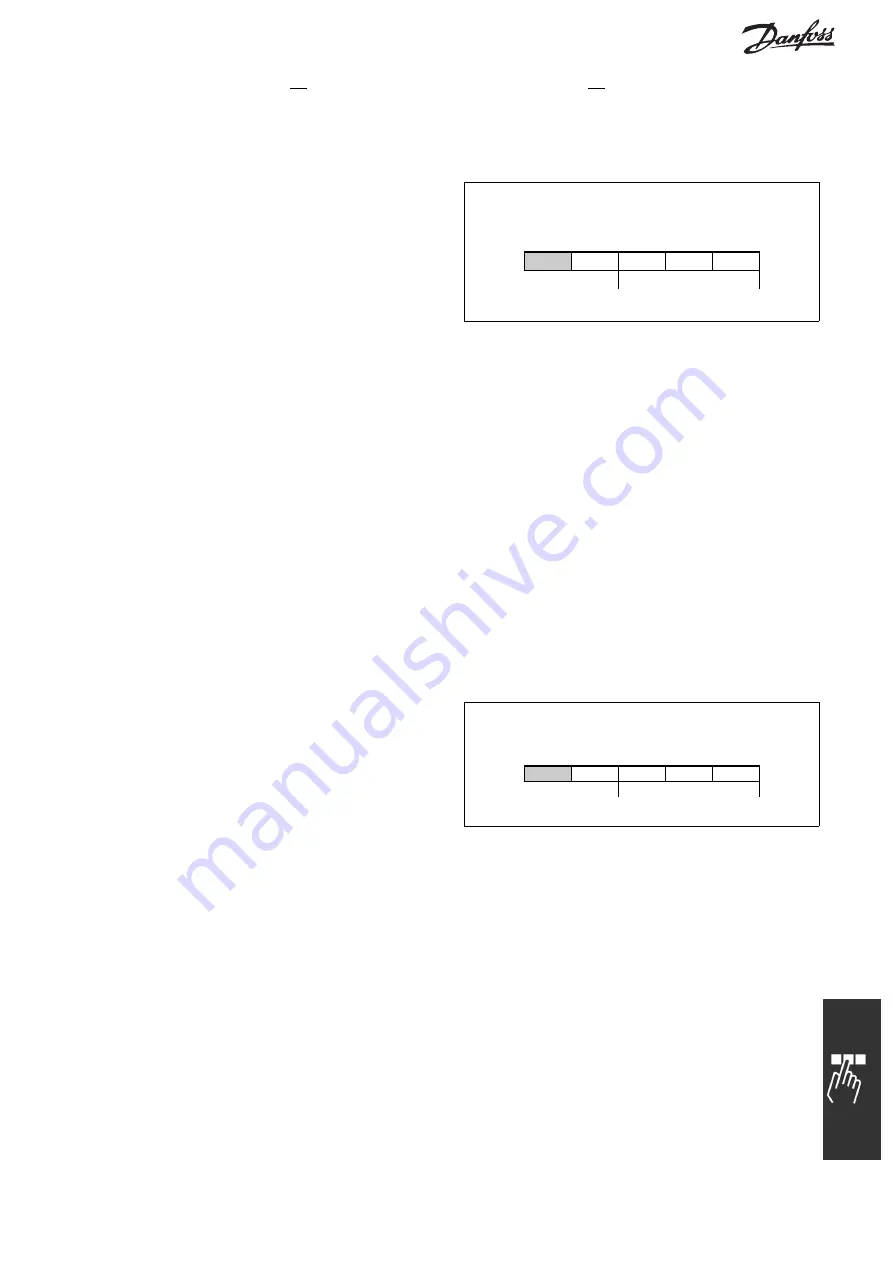
Process Control Data
Process data sent from the PLC to the FC 300 is
defined as Process Control Data (PCD).
Master
→
slave
1
2
3
......
10
CTW MRV PCD
......
PCD
PCD read/write
PCD 1 contains a 16-bit control word, where each bit controls a specific function of the FC 300, see section
Control Profile
. PCD 2 contains a 16-bit speed set point in percentage format. The value is transmitted in
integers (0-32767). The value 16384 (4000 Hex) corresponds to 100%. Negative numbers are formed
with the aid of the twos complement.
The bus reference value has the following format:
Par. 3-00
Reference range
= [0]:
refMIN
→
refMAX (0 - 100%)
0-16384 (0 - 4000 Hex)
Par. 3-00
Reference range
= [1]:
-refMAX
→
+ refMAX ( -100
→
+ 100%)
-16384
→
+ 16384 (8000
→
4000 Hex)
where the value 4000h represents 100% speed of the FC 300.
The content of PCD 3 to PCD 10 is programmed in par. 9-15
PCD write configuration
and par. 9-16
PCD
read configuration
.
Process Status Data
Process data sent from the FC 300 contains
information about the current state of the FC 300.
Slave
→
master
1
2
3
......
10
STW MAV
PCD
......
PCD
PCD read/write
PCD 1 contains a 16-bit status word, where each bit contains information regarding a possible state of
the FC 300.
PCD 2 contains the value of the current speed of the FC 300 in percentage format.
The value is transmitted in integers (0-32767). The value 16384 (4000 Hex) corresponds to 100%.
Negative numbers are formed with the aid of the twos complement.
The content of PCD 3 to PCD 10 is programmed in par. 9-16
PCD read configuration
.
27
MG.33.C2.02 - VLT is a registered Danfoss trademark


