background image

Montageanleitung / Installation Guide 


Verteilersysteme / distribution units - Multifamily

© Danfoss | Produced by Danfoss Redan A/S | 2017.05  | 21

VI.LZ.P1.5B

10. EINSTELLUNG UND INBETRIEBNAHME / ADJUSTMENT AND COMMISSIONING

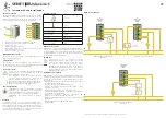
Elektrischer Anschluss

Der elektrische Anschluss des Systems darf nur von autorisiertem 
Personal durchgeführt werden. 
Die Station muss an eine Netzversorgung mit 230 VAC angeschlos-
sen werden. 
Die Stromversorgung/der Anschluss muss gemäß den geltenden 
Vorschriften und Anweisungen eingerichtet/vorgenommen werden. 
Die Station muss an einen externen Schalter angeschlossen werden, 
sodass sie für Wartungs-, Reinigungs und Reparaturarbeiten oder 
bei Notfällen vom Netz getrennt werden kann.

Nicht vergessen, 

Potentialausgleich gemäß den geltenden lokalen 

Vorschriften ausführen.

Montage von Außentemperaturfühler 

Der Außentemperaturfühler wird lose mitgeliefert und muß bauseits
laut Abbildungen montiert werden.
Den Fühler immer an der kältesten gebäudewand (normalerweise
die Nordseite) befestigen.
Der Fühler darf nicht der Morgensonne ausgesetzt sein, und darf 
nicht über Fenster, Türen, Luftabzügen oder anderen Wärmequellen, 
sowie nicht unter Balkone und Dachtraufen angebracht werden.

Montagehöhe ungefähr 2,5 m über dem Boden.
Temperaturbereich: -50 bis 50° C

Elektrischer Anschluss

Die Leiter können beliebig angeschlossen werden.
Anschlusskabel: 2 x 0,4 - 1,5 mm²

Kabelende am Regler an die Klemmen 29 und 30 anschließen.

Electrical connection

The electrical connection of the unit must be performed by aqualified 
and authorised electrician in compliance with all applicable rules 
and regulations.
The unit should be connected to a 230 V AC power supply.
The power supply / connection must be carried out in accordance
with the applicable regulations and instructions.
The unit must be wired and connected to an external main switchso 
that it can be disconnected during maintenance, cleaning and 
repairs or in the event of an emergency.

Do not forget

 to establish potential equalization in accordance

with the applicable regulations and instructions.

Mounting of outdoor sensor 

The outdoor temperature sensor is delivered separately and must 
be mounted on site according to the enclosed illustrations.

The outdoor sensor is always to be mounted on the coldest side of 
the property (normally the north side of the property). 
The sensor must not be exposed to the morning sun, and should not 
be mounted above windows, doors, air vents or other heat sources, 
and not under balconies and roof eaves.

Mounting height approx. 2.5 m above ground.
Temperature range: -50 to 50° C.

Electrical connections

Two wire non polarized (can be crossed).
Sensor cable: 2 x 0.4 - 1.5 mm².

Connect the cable ends to ECL controller in clamps 29 and 30.

Regler / Controller ECL 310

Versorgungsspannung /
Power supply: 

230 V a.c. - 50 Hz

Toleranzbereich der
Versorgungsspannung: 

207 to 244 V a.c. (IEC 60038)

Leistungsaufnahme / 
Power consumption: 

5 VA

Belastung der Relaisausgänge /
Load on relay outputs: 

4(2) A - 230 V a.c

Belastung der Triac-Ausgänge /
Load on triac outputs: 

0,2 A - 230 V a.c.

Stellantrieb / Actuator AMV 140

Versorgungsspannung /
Power supply: 

230 AC; +10 to –15 % - 50/60 Hz

Schutzart / Protection class: 

IP 42

Leistungsaufnahme / 
Power consumption: 

8 VA

Pumpe / Pump Yonos Para

Versorgungsspannung /
Power supply: 

                   230 V AC – 50 Hz

Leistungsaufnahme / 
Power consumption:                     Max. 31 Watt 
Schutzart / Protection class:        IP42 

Für weitere Informationen siehe bitte beigelegte Anleitungen / 
For further information please refer to the enclosed instructions.


GERMAN - DE


ENGLISH - GB

Summary of Contents for E-SGTZCM

Page 1: ...eilersysteme mitMessstation distributionsystems withmeteringunit Danfoss vorgefertigte EdelstahlVerteilersysteme f r Fussbodenheizung Danfoss prefabricated solutions for floor heating Edelstahl Vertei...

Page 2: ...s 13 8 0 Montage Mounting 15 9 0 Montage im Einbauschrank Mounting in recess box 16 10 0 Einstellung und Inbetriebnahme Adjustment and commissioning 18 11 0 Regeltechnik Fussbodenheizung Control Floor...

Page 3: ...ehobenwerden ZumTrans portieren Bef rdern ber gro e Entfernungen m ssen die Verteil ersysteme auf Paletten platziert werden HebenSiedieVerteilersystemenachM glichkeitnichtandenRohren an da dadurch Lec...

Page 4: ...by the pipes Retighten ALL pipe connections after transport moving Disposal Dispose of the packaging in accordance with the local regulations for disposal of used packaging materials The unit is made...

Page 5: ...Aus diesem Grund ist es wichtig dass Sie die berwurfmutternNICHTZUFEST ANZIEHEN Zu fest angezogene berwurfmuttern k nnen zu Leckagen f hren Leckagen die durch zufestangezogene berwurfmutternoderdurch...

Page 6: ...150 mm und H910 B850 T150 mm Die Breite 690 mm passt zu Verteilersystemen mit bis zu 8 Heizkreisen Die Breite 850 mm passt zu Verteilersystemen mit bis zu 12 Heizkreisen Montagef sse f r die Unterputz...

Page 7: ...ung Type SGCM Distribution systems with AB PM a combined automatic balancing valve with flow limiter and integrated control valve SS FH manifold safety thermostat STW 55 C TWA air vents and strainer i...
Page 8: ...und Schmutzf nger imVorlauf und R cklauf Mit elektronisch geregeltem Mischkreis Hocheffizienzpumpe und Einzelraumregelung Type E SGTZCM Distribution systems with AB PM a combined automatic balancing v...

Page 9: ...s 145H0568 Typ SGTZM mit 9 Heizkreisen mit thermostatischem Mischkreis 145H0569 Typ SGTZM mit 10 Heizkreisen mit thermostatischem Mischkreis 145H0570 Typ SGTZM mit 11 Heizkreisen mit thermostatischem...

Page 10: ...g circuits with thermostatic mixing loop 145H0568 Type SGTZM with 9 heating circuits with thermostatic mixing loop 145H0569 Type SGTZM with 10 heating circuits with thermostatic mixing loop 145H0570 T...

Page 11: ...u Hochtemperaturkreis High temperature connection 52 Thermischer Stellantrieb TWA Z Thermal actuator TWA Z 54 Sicherheitsthermostat Safety thermostat 57 Netzstecker Plug 58 Anschlussverteiler mit Durc...

Page 12: ...IZZE ANSCHLUSS DIMENSIONAL SKETCH CONNECTION FH Supply FH Vorlauf FH Return FH R cklauf DHSupply FW Vorlauf DH Return FW R cklauf MASSSKIZZE DIMENSIONAL SKETCH 754 593 129 11 07 2016 DHSupply FW Vorla...

Page 13: ...hahn Ball valve 10 Umw lzpumpe WILO YONOS 15 6 130 230V Circulation pump Wilo Yonos 15 6 130 230V 17 Entl ftung Air vent 19 Entleerungshahn und manueller Entl fter Tapping point with manual air vent 2...

Page 14: ...vent 19 Entleerungshahn und manueller Entl fter Tapping point with manual Air vent 24 Pa st ck f r W rmemengenz hler Fitting piece for heat meter 25 Elektronische Regler ECL Comfort Electronic control...

Page 15: ...k H910 B690 T150 mm 9 12 Kreise passen in den 145H4281 Unterputzschrank H910 B850 T150 mm The distributors fits on the back plate of the recess boxes and also be mounted on the wall The systems can be...

Page 16: ...ce with the labelling on the unit and or in accordance with the instruc tions in this manual Schritt Unterputzschrank wird eingemauert oder in Leichtbauwand eingebaut Step Recess box with rotatable mo...

Page 17: ...ohranschlu ist Step Installer connects the household pipes for DH supply and DH return and insulates the pipes When installing please ensure that there is enough space for pipe connection Schritt Befe...

Page 18: ...UNG UND INBETRIEBNAHME ADJUSTMENT AND COMMISSIONING Verteiler mit Anschl ssen mit Durchflussmesser Durchflussmenge l ss sich durch Drehen des Durchflussmessers einstellen Siehe bitte beigelegte Abbild...

Page 19: ...Montageanleitung Installation Guide Verteilersysteme distribution units Multifamily Danfoss Produced by Danfoss Redan A S 2017 05 19 VI LZ P1 5B von oben...

Page 20: ...n abbauen Pos A Der eine Temperaturf hler in die F hlertasche einstecken Der berwurfmutter des F hlers festschrauben Der andere F hler imW rmemengenz hlergeh use auf FW R cklauf einbauen und festschra...

Page 21: ...C power supply The power supply connection must be carried out in accordance with the applicable regulations and instructions The unit must be wired and connected to an external main switchso that it...

Page 22: ...rlaubsbetrieb usw verf gbar Siehe bitte beigelegte Instruktionsanleitung f r weitere Informa tionen Generell Ontheprimarysidetheunitsaresuppliedwithacombinedautomatic balancing valve AB PM which acts...

Page 23: ...eier MNG Oventrop valves with M30 1 5 connection generally as per attached drawing Other valves must be verified individually to ensure correct valve closing measurement and valve top geometry TWA D F...

Page 24: ...estattet Siehe bitte beigelegte Bedienungsanleitungen ber Danfoss ECL 310 und Wilo Yonos Para Pumpe Mixing circuit Distribution systems SGTCM SGTZCM and E SGTZCM include an integrated mixing circuit S...

Page 25: ...ksichtigung des Komfortanspr che so nie drig wie berhaupt m glich ist ca 30 35 Die Vorlauftemperatur soll nie 45 C berschreiten IMMER die In struktionen des Fussbodenlieferanten beachten Thermostatic...

Page 26: ...g Installation Guide Verteilersysteme distribution units Multifamily 26 Danfoss Produced by Danfoss Redan A S 2017 05 VI LZ P1 5B Schaltdiagramm Wiring diagram 11 REGELTECHNIK FUSSBODENHEIZUNG CONTROL...

Page 27: ...pplication by means of an ECL Application Key Plug Play The Application Key contains information about application languages and factory settings VariousapplicationscanbeloadedbymeansoftheECLApplicati...

Page 28: ...as Ventil geschlossen Liegt keine Kraft vom Stellantrieb an ffnet die ventilinterne Feder das Ventil 1 Installation Guide TWA Z Gen 2011 Heating Solutions VI SB I6 02 SMT SI TWA Z AB QM 24 V Class III...

Page 29: ...pe in Abh ngigkeit vom Heizbedarf des Geb udes auf die niedrigstm gliche Position unter Ber cksichti gung von Aspekten wie K hlung und Leistungsaufnahme Entl ften Entl ften Sie das System mit den Entl...

Page 30: ...ernen Energieversorgung einschalten und von Leckagen berwachen Anlage entl ften Wenn n tig die Anlage neu einstellen Sicherstellen dass alle Sicherheitseinrichtungen des Ger tes und der Anlage wieder...

Page 31: ...Montageanleitung Installation Guide Verteilersysteme distribution units Multifamily Danfoss Produced by Danfoss Redan A S 2017 05 31 VI LZ P1 5B 14 EU GUTACHTEN EU DECLARATION OF CONFORMITY...

Page 32: ...hf hren Beim Einbau sind alle rtlichen Standards und Vorschriften einzuhalten Installation und erste Inbetriebnahme d rfen nur von qualifizierten und autorisierten Personen durchgef hrt werden Die Sta...

Page 33: ...technical regulations and the applicable legislation in every respect Installation and commissioning must only be performed by trained authorised personnel The unit is checked in the factory for leak...

Page 34: ...Montageanleitung Installation Guide Verteilersysteme distribution units Multifamily 34 Danfoss Produced by Danfoss Redan A S 2017 05 VI LZ P1 5B...

Page 35: ...Montageanleitung Installation Guide Verteilersysteme distribution units Multifamily Danfoss Produced by Danfoss Redan A S 2017 05 35 VI LZ P1 5B...

Page 36: ...orherige Bekanntmachung im Rahmen des Angemessenen und Zumutbaren nderungen an ihren Produkten auch an bereits in Auftrag genommenen vorzunehmen Alle in dieser Publikation enthaltenen Warenzeichen sin...

Reviews: