ro-solutions.com
User manual
Installation, Operation and
Maintenance Manual
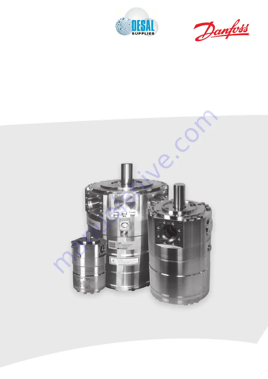
APP S 674 pumps
MAKING MODERN LIVING POSSIBLE
Tel:
+44
(0)
1706
869777
E
‐
mail:
[email protected]
Web:
www.desal.co.uk
Page 1: ...ro solutions com User manual Installation Operation and Maintenance Manual APP S 674 pumps MAKING MODERN LIVING POSSIBLE Tel 44 0 1706 869777 E mail sales desal co uk Web www desal co uk...
Page 2: ...nspection transportation handling lifting and storage 9 4 1 Arrival inspection 9 4 2 Warning 9 4 3 General safety information 9 4 4 Transport and handling 9 4 5 Return to supplier 10 4 6 Storage 10 5...
Page 3: ...r mounting the pump onto the electric motor 15 7 7 Getting the pump unit back into operation 15 7 8 Storage of the pump 15 8 Troubleshooting and scrapping criteria 16 8 1 General safety information 16...
Page 4: ...no 02 APP S 674 5 1 Code no 180B7050 Serial no 02 APP S 674 6 5 Code no 180B7051 Serial no 02 APP S 674 7 2 Code no 180B7052 Serial no 02 APP S 674 8 2 Code no 180B7055 Serial no 02 APP S 674 9 0 Code...
Page 5: ...5 180R9270 IOM APP S 674 v01 03 2013 EU Declaration of Conform ity...
Page 6: ...ing the unit Servicing the pump unit mechanical and electrical parts Decommissioning the pump unit The pump must always be installed and used in accordance with existing national local sanitary safety...
Page 7: ...is ATEX certified the additional ATEX instruction must also be read Protective garments must be worn Always wear suitable safety clothing when handling the pump When working near the pump system safet...
Page 8: ...isted in section 1 3 Manufacturer and customer service address 3 1 Approved applications and operational limits for the pumps The pump and the pump unit are designed for the use in a Sea Water Reverse...
Page 9: ...sed to any chemicals as it can result in damage to piping equipment and internal parts in the pump 4 Arrival inspection transportation handling lifting and storage 4 1 Arrival inspection The pump is p...
Page 10: ...ting the pump unit one sling must be attached to the electric motor and one sling around the pump Some motors and pumps have specific lifting eyes Do not use connections nozzles for lifting Do not use...
Page 11: ...irt or rust is not removed the pump and the valves can be damaged In worst case the pump can be damaged beyond repair 5 3 Fluid temperature Before start up the fluid and pump housing temperature must...
Page 12: ...pider 3 5 mm see Instruction appendix 2 CP12 Check correct connections on the pump in outlet CP13 Check piping for possible air gaps 5 7 Lifting and positioning Lift the pump unit onto base Remember v...
Page 13: ...ng not available on all bell housings If the motor is turning the wrong direction switch two phases in the connection box of the motor or reprogram the direction in VFD When the motor is turning in th...
Page 14: ...nstruction If the pump is not stopped for inspection as recommended it can lead to damage of the pump or breakdown See also service and warranty section in appendix 1 Data sheet or appendix 2 Instruct...
Page 15: ...at www ro solutions danfoss com Clean all the parts and surfaces with a fluid compatible with the materials found in the pump Wipe the parts clean and dry with a lint free clothing C Inspect all part...
Page 16: ...et can cause eye or skin damage Leakage can result in flooding which can cause slipping tripping or falling If water is leaking into the electric motor it can cause electric shock fire short circuit o...
Page 17: ...ro solutions com User manual Appendices for Installation Operation and Maintenance Manual APP S 674 pumps Appendices APP S 674 pumps...
Page 18: ...S 674 pumps 18 180R9270 IOM APP S 674 v01 03 2013 Data sheet APP S 674 pumps 521B1187 21 Pump instruction APP S 674 180R9276 39 Parts list APP S 674 pumps 521B1248 51 Trouble shooting guide for APP p...
Page 19: ...Data sheet APP S 674 pumps 521B1187 ro solutions com Data sheet APP S 674 pumps APP S 674 3 0 3 5 APP S 674 5 1 9 0 APP S 674 21 38 MAKING MODERN LIVING POSSIBLE...
Page 20: ...sion 7 Motor requirements 8 Installation 8 1 Filtration 8 2 Noise 8 2 1 APP S 674 3 0 3 5 pump mounted on motor 5 5 kW 4 pole 11 kW 2 pole 8 2 2 APP S 674 5 1 9 0 pump mounted on motor 22 kW 4 pole 8...
Page 21: ...d corrosive fluids under high pressure e g in seawater reverse osmosis applications Danfoss APP S 674 pumps are positive displace ment pumps with axial pistons that move a fixed amount of water in eac...
Page 22: ...cal Flow 1500 rpm at max pressure m3 h 1 5 1 75 3000 rpm at max pressure m3 h 3 0 3 5 1800 rpm at max pressure gpm 7 9 9 3 3000 rpm at max pressure gpm 13 3 15 4 Typical motor size 1500 rpm at max pre...
Page 23: ...ed continuous rpm 1800 1800 1800 1800 1800 Typical Flow 1000 rpm at max pressure m3 h 2 7 3 4 3 8 4 5 5 1 1800 rpm at max pressure m3 h 5 0 6 4 7 2 8 3 9 3 1200 rpm at max pressure gpm 14 3 18 0 20 3...
Page 24: ...00 Max speed continuous rpm 1500 1500 1500 1500 1500 1500 Typical Flow 700 rpm at max pressure m3 h 10 11 12 14 15 2 17 5 1500 rpm at max pressure m3 h 21 9 24 2 26 7 31 3 33 3 38 4 700 rpm at max pre...
Page 25: ...elow diagram can be used to select the pump that fits the application best 5 1 APP S 674 3 0 3 5 flow curves at max pressure 5 Flow 4 0 3 5 3 0 2 5 2 0 1 5 1 0 0 5 APP S 674 3 5 APP S 674 3 0 rpm m3 h...
Page 26: ...8 0 0 APP S 674 5 1 APP S 674 6 5 APP S 674 7 2 APP S 674 8 2 APP S 674 9 0 1 2 3 4 5 6 7 8 9 10 m3 h rpm rpm APP S 674 9 0 APP S 674 8 2 APP S 674 7 2 APP S 674 6 5 APP S 674 5 1 42 38 34 30 26 22 18...
Page 27: ...Typical flow 170 160 150 140 130 120 110 100 90 80 70 60 50 40 gpm rpm 7 0 0 8 0 0 9 0 0 1 0 0 0 1 1 0 0 1 2 0 0 1 3 0 0 1 4 0 0 1 5 0 0 APP S 674 21 APP S 674 26 APP S 674 33 APP S 674 38 APP S 674...
Page 28: ...e water to flow from inlet to outlet when the pump is not running Pressure drop bar 3 5 3 2 5 2 1 5 1 0 5 0 0 1 2 3 4 5 6 7 Kurver P1 0 0 5 1 1 5 2 2 5 3 3 5 0 1 2 3 4 5 6 7 P Bar Flow m3 h Trykfaldsk...
Page 29: ...the risk of crevice corrosion 316L Super Duplex 80 C 70 60 50 40 30 20 100 160 1600 1000 16000 10 000 160000 100 000 CI ppm NaCI ppm Duplex The power requirements can be determined using one of the fo...
Page 30: ...gh them compare this to precision depth filters that are 99 98 efficient and only allow 20 of the same 100 000 particles to pass through For more information on the importance of proper filtration inc...
Page 31: ...1 m dB A Speed RPM APP S 674 5 1 9 0 22 kW 4 pole motor Linear 60 Bar Linear 80 Bar Rotation speed rpm Sound pressure level L PA 1 m dB A 6 0 0 8 0 0 1 0 0 0 1 2 0 0 1 4 0 0 1 6 0 0 1 8 0 0 2 0 0 0 2...
Page 32: ...line a low pressure relief valve is also required between the non return valve and the pump to protect against high pressure peaks 1 4 5 3 PI PS M 5 2 6 8 4 RO system with APP S 674 pump The numbers...
Page 33: ...cessories Type inlet flange ASME B16 5 outlet flange ASME B16 5 Description APP S 674 3 0 3 5 Parallel key DIN 6885 mm in 5 5 5 0 20 0 20 0 78 Bleeding M6 Hexagon Allen key 5 mm Inlet port 4 bolt flan...
Page 34: ...inlet flange ASME B16 5 1 outlet flange ASME B16 5 Description APP S 674 5 1 9 0 Parallel key DIN 6885 mm in 10 8 45 0 39 0 31 1 77 Bleeding G Hexagon Allen key 6 mm Inlet port 8 bolt flange Outlet p...
Page 35: ...nlet flange ASME B16 5 2 outlet flange ASME B16 5 Description APP S 674 21 38 Parallel key DIN 6885 mm in 12 8 70 0 47 0 31 2 76 Bleeding G Hexagon Allen key 8 mm Inlet port 8 bolt flange Outlet port...
Page 36: ...s are designed for long operation low maintenance and reduced lifecycle costs Provided that the pump has been running according to the Danfoss specifications Danfoss guarantees 8 000 hours service fre...
Page 37: ...Pump instruction APP S 674 180R9276 ro solutions com Instruction APP S 674 pumps APP S 674 3 0 3 5 APP S 674 5 1 9 0 APP S 674 21 38 MAKING MODERN LIVING POSSIBLE...
Page 38: ...n of rotation 3 3 Orientation 3 4 Connections 3 4 1 APP S 674 3 0 3 5 3 4 2 APP S 674 5 1 9 0 3 4 3 APP S 674 21 38 4 Initial start up 4 1 APP S 674 3 0 3 5 4 2 APP S 674 5 1 9 0 4 3 APP S 674 21 38 5...
Page 39: ...let line a low pressure relief valve is also required between the non return valve and the pump to protect against high pressure peaks 2 System design 1 4 5 3 PI PS M 5 2 6 2 2 RO system with APP S 67...
Page 40: ...longest distance A from top of bell housing to the button of coupling claw 4 Mount the coupling on the motor shaft Ensure the coupling and motor flange are not in contact with each other 2 3 Protecti...
Page 41: ...tor After mounting it must be possible to move the flexible gear ring 3 5 mm 0 12 0 2 in axial C The check can be done through the inspection hole of the bell housing Secure flange bolts with the righ...
Page 42: ...3 Z1 02 03 2013 3 4 Connections 3 4 1 APP S 674 3 0 3 5 3 4 2APP S 674 5 1 9 0 4 x M8 x 1 25 12 depth 49 82 1 961 Inlet Outlet Mounting of flange connections Bolt torque 30 3 Nm 22 2 lbf ft Mounting o...
Page 43: ...al hexagan sockets Retighten the plug when water appears from the bleeding plug 4 Make sure that the direction of rotation of the electric motor corresponds to the direction of rotation of the pump se...
Page 44: ...r inlet pressure than stated in above table the pump will cavitate which will damage the pump The inlet line connection must be properly tightened as entrance of air will cause cavitation Outlet press...
Page 45: ...r for temperatures below the freezing point flush the pump with an anti freeze medium type monopropylene glycol to prevent internal corrosion or frost in the pump For furter information on anti freeze...
Page 46: ...re not followed it will strongly influence the life of the APP S 674 pumps Maintenance After 8 000 hours of operation it is strongly recommended to inspect the pump and change any worn parts e g pisto...
Page 47: ...0 000 hours 65 1 1 1 Retainer plate Super Duplex 24 000 hours 64 1 1 1 Retainer ball Super Duplex 40 000 hours 71 1 1 Retainer guide Super Duplex PEEK 40 000 hours 62 1 1 4 Spring Hastelloy C4 40 000...
Page 48: ...48 180R9270 IOM APP S 674 v01 03 2013 12 180R9276 521B1245 DKCFN PI 013 Z1 02 03 2013 10 EC Declaration of Conformity...
Page 49: ...49 180R9270 IOM APP S 674 v01 03 2013 Instruction APP S 674 pumps 13 180R9276 521B1245 DKCFN PI 013 Z1 02 03 2013...
Page 50: ...rves the right to alter its products without notice This also applies to products already on order provided that such alterations can be made without subsequential changes being necessary in specifica...
Page 51: ...Parts list APP S 674 pumps 521B1248 ro solutions com Parts list APP S 674 pumps APP S 674 3 0 3 5 APP S 674 5 1 9 0 APP S 674 21 38 MAKING MODERN LIVING POSSIBLE...
Page 52: ...52 180R9270 IOM APP S 674 v01 03 2013 Parts list APP S 674 pumps 2 521B1248 DKCFN PY 073 G1 02 03 2013...
Page 53: ...rts list provides an overview of the content of the various service sets for the APP S 674 3 0 3 5 APP S 674 5 1 9 0 APP S 674 21 38 as well as exploded views of the pumps 1 General Our CLP RO pumps h...
Page 54: ...lex x1 65 1 Retainer plate Super Duplex x1 66 7 Piston Super Duplex PEEK x1 67 1 Key AISI 316 x 91 1 Port plate Super Duplex PEEK x 92 1 Valve plate Super Duplex x1 93 7 Back up ring PTFE x 94 7 O rin...
Page 55: ...55 180R9270 IOM APP S 674 v01 03 2013 Parts list APP S 674 pumps 5 521B1248 DKCFN PY 073 G1 02 03 2013 3 Exploded view APP S 674 3 0 3 5...
Page 56: ...Super Duplex x1 65 1 Retainer plate Super Duplex x1 66 9 Piston Super Duplex PEEK x1 67 1 Key AISI 316 x 71 1 Retainer guide Super Duplex PEEK x1 91 1 Port plate Super Duplex PEEK x 92 1 Valve plate...
Page 57: ...57 180R9270 IOM APP S 674 v01 03 2013 Parts list APP S 674 pumps 7 521B1248 DKCFN PY 073 G1 02 03 2013 5 Exploded view APP S 674 5 1 9 0...
Page 58: ...Duplex PEEK x 62 4 Spring Hastelloy C276 x x 63 1 Spring guide PP x x 64 1 Retainer ball Super Duplex x x 65 1 Retainer plate Super Duplex x x 66 9 Piston Super Duplex PEEK x 67 1 Key AISI 316 x 71 1...
Page 59: ...59 180R9270 IOM APP S 674 v01 03 2013 Parts list APP S 674 pumps 9 521B1248 DKCFN PY 073 G1 02 03 2013 7 Exploded view APP S 674 21 38...
Page 60: ...l changes being necessary in specifications already agreed All trademarks in this material are property of the respective companies Danfoss and the Danfoss logotype are trademarks of Danfoss A S All r...
Page 61: ...Trouble shooting guide for APP pumps ro solutions com Guideline Trouble shooting guide for APP and APP S 674 pumps MAKING MODERN LIVING POSSIBLE...
Page 62: ...013 Trouble shooting fish bone chart 1 No flow no pressure 2 Reduced flow reduced pressure 3 High torque on electric motor 4 Noise from pump 5 Noise from installation 6 Typical signs of wear 6 1 Valve...
Page 63: ...8 Main filtration 2 1 Wear in pump internal leakage 2 1 9 Type of fluid 2 1 11 High fluid temperature 4 1 Air in fluid 4 2 Bleeding conditions of pump 4 3 Min max nominal inlet pressure 4 4 Pump rever...
Page 64: ...or is capable of running with no load If motor type relay or the electrical fuse is blown check that electric motor is sized correctly 1 4 No rotation of pump 1 4 1 Ensure that coupling between electr...
Page 65: ...dex 6 3 If the ring is missing the piston is very worn The filters can be bypassed even if they are correctly mounted Some filters can create channelling where particles can pass trough the filter in...
Page 66: ...ressure resulting in higher motor torque 3 2 Pump starts against pressure 3 2 1 Check that electric motor is correctly sized 3 2 2 Check internal parts see item 2 1 3 2 3 Systems with more than one el...
Page 67: ...4 4 Pump reversing 4 4 1 Dismantle pump and check if anything is broken or worn See 1 No flow item 1 2 Pump reversing WARNING The pump must not run without water for more than a few seconds If the pum...
Page 68: ...oo many bends may create too fast flow turbulence through the pipes and thus increase the noise level 5 3 Hose stiffness 5 3 1 Use a more flexible hose Danfoss can provide flexible hoses Please contac...
Page 69: ...te has scratches and or a polished surface Even small scratches will give a loss of flow Picture 3 A good way to identify a worn valve plate is to hold a straight knife edge over the valve plate When...
Page 70: ...marks of Danfoss A S All rights reserved Danfoss A S High Pressure Pumps DK 6430 Nordborg Denmark Picture 1 If the port plate has scratches level differences or both between the arrows the port plate...
Page 71: ...User manual Appendices APP S 674 pumps 71 180R9270 IOM APP S 674 v01 03 2013...
Page 72: ...27 28 32 39 45 64 65 67 68 69 70 Flow curves 25 26 27 Fluid 11 12 15 16 21 30 65 66 67 Flush 8 11 13 21 28 29 32 36 39 43 45 46 Flushing valve 21 28 43 G General information 7 Guideline 16 36 61 64 H...