D
INSTALLATION
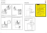
6. Mount unit cabinet to the wall. Insert power cord
through the inlet hole located in the back of the cabinet, or
through the premade opening at the bottom of the cabinet.
Connect power cord to hand dryer. It may be necessary to
remove a plate to push the cord through.
POWER CORD
8. Remove end cap from blind plug. Pull wires and earthing
through the flexi hose and air branch on motor. Fasten the
flexi hose to the cabinet branch. Attach the opposite end of
the flexi hose to branch on tap.
BLIND PLUG
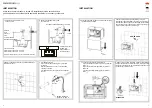
INSTALLATION
Make sure the main breaker is turned off. Installation must be carried out by a
qualified person in accordance with applicable standards in the country concerned.
3. Mark the desired postion on the wall and drill a Ø35
mm diameter hole.
4. Installation of the tap:
A) Push the screwed bushing through the hole
in the wall
B) Place gasket, disc, and nut on the threaded
coupling of the tap
C) Tighten with tool, be careful not to overtighten
the nut.
Recommended wall
thickness: 10-30 mm
Gasket
Disc
Nut
5. Unscrew (2) bottom screws and remove cabinet using
the allen wrench included .
1. Check the required distance from
sensor to sink.
30°
Ceramic ≥250 mm
Brushed steel ≥300 mm
Sensor
Sensor field of view:
Object distance 250 mm: D: ≤128 mm
Object distance 300 mm: D: ≤155 mm
Objects within range D may cause unintentional activation.
160
D
2. Check the required distance from
sensor to sink.
Recommended wall thickness: 10-30 mm
19 mm
≥170mm
30°
Sensor
A minimum distance
of 180 mm is
required between
each tap product.
≥180 mm
Distance
from
sensor to
sink:
7. Connect supply wires to terminal block:
A) Connect phase wire (black or brown) to terminal
block ”L”.
B) Connect neutral wire (light blue) to terminal
block ”N”.
C) Connect earthing (yellow/green) to terminal
block ” ”
6
7


