English
Rev. 1.0.4 / 101006
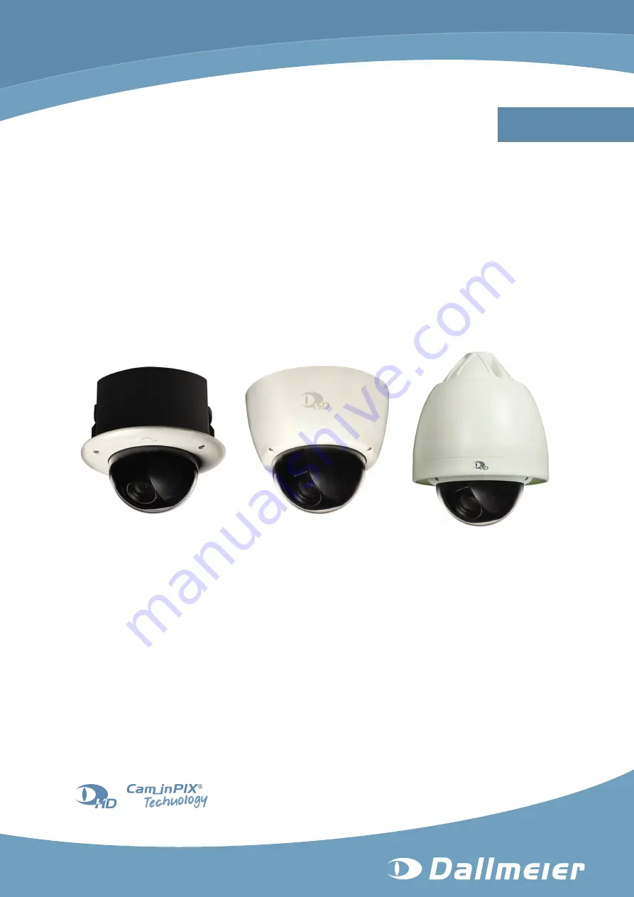
Installation and Configuration
Vandal-resistant High Definition IP Dome Camera
DDF4010HDV
1080p
-SM
(Surface Mount Variant)
-IM
(In-ceiling Mount Variant)
-WM
(Weather-proof Variant)
Page 1: ...English Rev 1 0 4 101006 Installation and Configuration Vandal resistant High Definition IP Dome Camera DDF4010HDV 1080p SM Surface Mount Variant IM In ceiling Mount Variant WM Weather proof Variant...
Page 2: ...93051 Regensburg Germany www dallmeier com info dallmeier com All trademarks identified by are registered trademarks of Dallmeier electronic All trademarks identified by are trademarks or registered...
Page 3: ...ction Assignment 13 5 1 In ceiling Mount Variant 13 5 2 Surface Mount Variant 15 5 3 Weather proof Variant 18 6 Installation and Commissioning 19 6 1 In ceiling Mount Variant 19 6 2 Surface Mount Vari...
Page 4: ...ion 51 10 2 3 White Balance 52 10 2 4 Day Night 53 10 3 Encoder Settings 54 10 3 1 Encoder 1 54 10 3 2 Encoder 2 56 10 3 3 Audio 56 11 Interfaces 57 11 1 Serial Interface 57 11 2 Relays 57 11 3 Data D...
Page 5: ...DDF4010HDV www dallmeier com 5 17 Technical Data 72 18 Technical Drawings 74 18 1 In ceiling Mount Variant 74 18 2 Surface Mount Variant 75 18 3 Weather proof Variant 76...
Page 6: ...he connec tion and commissioning of the device Installation and Configuration this document The document entitled Installation and Configuration contains detailed descriptions of the installation conn...
Page 7: ...operations Instructions are indicated by arrows Expressions in bold italics generally indicate a control element on the device switches or labels or on its user interface buttons menu entries Paragra...
Page 8: ...of warranty Modifications Do not make any modifications to the hardware or software that has not been tested and approved by Dallmeier Inappropriate modifications can cause malfunctions damages and d...
Page 9: ...wer supply pull out the power plug Contact the sales partner responsible for your area Opening The housing of the unit may only be opened by qualified personnel for commissioning inspection maintenanc...
Page 10: ...at the packaging used sufficiently protects the unit against damage moisture heat and cold 3 3 Appropriate Use The DDF4010HDV is a vandal resistant High Definition IP dome camera The in ceiling mount...
Page 11: ...le device variants in ceiling mount surface mount and weather proof variant Compact vandal resistant housing with IP67 surface mount and weather proof variant only DIN EN 50130 4 compliant For detaile...
Page 12: ...e device with power over Ethernet Note that the built in heater of the weather proof variant must be separately supplied with 24V AC max 3A if required 4 3 Outdoor For outdoor installations use the we...
Page 13: ...Assignment 5 1 In ceiling Mount Variant M6 screw eye bolt Ceiling clamp Trim ring with bubble Housing Terminal area Lens Ceiling clamp Housing screw T20 Torx Fig 5 1 Ceiling clamp M6 screw eye bolt Le...
Page 14: ...eier com 14 M4 locking screw ceiling clamp Thread for housing screw USB SD port Video preview output 3 5mm phone jack M4 locking screw ceiling clamp Fig 5 3 3 axis mount pan tilt rotation WIDE button...
Page 15: ...read for housing screw Housing base Slot for spring clip 1 Securing screw spring clip 2 Video preview output 3 5mm phone jack USB SD port Housing with bubble Housing screw T20 Torx Lens Plug in module...
Page 16: ...ousing screw Thread for housing screw Mounting hole for 4mm screw Thread for PG16 cable gland Slot for spring clip 2 Terminal area Fig 5 6 Securing screw spring clip 1 Securing screw spring clip 1 Plu...
Page 17: ...DDF4010HDV www dallmeier com 17 Plug in module Securing screw spring clip 2 Securing screw spring clip 1 Spring clip 1 3 axis mount pan tilt rotation WIDE button TELE button Spring clip 2 Fig 5 8...
Page 18: ...hite GND I O Gray White GND I O Purple White GND I O 3 Power IN 24V AC 1 8 Ethernet RJ45 Pin 1 1 Fig 5 9 Power IN 24V AC for camera unit Pin No Assignment 1 24V AC 2 Not used 3 24V AC Note that the bu...
Page 19: ...ceiling wall material Use the correct type of anchor for your ceiling wall type Plastic screw anchors for solid wall material concrete brick Toggle bolt style anchors for drywall hollow wall type pla...
Page 20: ...e trim ring Suspended ceiling 169mm M6 screw eye bolt Ceiling clamp Ceiling clamp Trim ring with bubble Housing screw T20 Torx Fig 6 1 Step 2 Fig 6 2 Screw a ceiling hook on the supporting structure I...
Page 21: ...g hook Suspended ceiling Ceiling clamp Ceiling clamp Terminal area Fig 6 2 Step 3 Tighten the M4 locking screw Fig 5 3 of both ceiling clamps with a Phillips screw driver until the housing is fixed Fi...
Page 22: ...ig 5 3 Adjust the lens using the 3 axis mount and set the focal length with the TELE WIDE buttons Fig 5 4 The Little Man symbol on the lens side indicates the sensor direction Disconnect the CVBS moni...
Page 23: ...drill holes on the ceiling wall using the 3 pre drilled mounting holes of the housing base as a template At the marked locations drill holes fitting for the screws anchors to be used Push anchors suit...
Page 24: ...Securing screw spring clip 2 Plug in module Spring clip 2 Securing screw spring clip 2 Slot for spring clip 2 Fig 6 7 Connect the power supply unit to the mains socket Connect a CVBS monitor to the v...
Page 25: ...a more powerful PC is required if several devices are configured with live video display simultaneously a DirectX compatible graphics card and the Dallmeier control for ActiveX are not re quired for...
Page 26: ...witch between live and configuration mode C Live video D Adjust video resolution E IP address of device F Log out of configuration mode Note the explanations below Hide the title bar A if required Act...
Page 27: ...ckets the port 30000 for the DaVid Protocol1 and port 80 for the Hypertext Transfer Protocol HTTP must be open Note that at data transmission over TCP normally no packet loss lack of images occurs sho...
Page 28: ...Switch between live and configuration mode C IP address of device D Log out of configuration mode E Disable enable live video display F Live video G Configuration menu H Configuration dialogues Note...
Page 29: ...ia Common settings User interface Fig 8 1 Set the Language Deactivate the Show live video ActiveX in WebConfig checkbox if network bottle necks occur or your system is overloaded Confirm with OK 8 2 S...
Page 30: ...s enabled Select the Date Time tab Fig 8 3 Set the Date Set the Time Confirm with OK 8 2 2 Time Server Note that the time server must always be accessible via the network Select the Time server tab Fi...
Page 31: ...groups In addition several users can be assigned to each user group if required 8 4 1 Login Mode The configuration of the device is only possible after a successful authentication as a valid user The...
Page 32: ...ity reasons Group 2 user and Group 3 guest are defined without a factory default password a login of Group 2 user and Group 3 guest is only possible after a password is de fined Open the User groups d...
Page 33: ...Ensure that the Login mode is set to User login Open the User groups dialogue via Common settings User management User groups Fig 8 8 Select the tab of the relevant group Click New The New user dialo...
Page 34: ...ton 8 4 4 Rights The three user groups and so the assigned users can be granted individual rights Ad ditionally the general public user group anonymous can be granted or denied access to certain types...
Page 35: ...d The settings can be changed The function can be used allow read only The dialogue will be displayed The settings can not be changed deny The dialogue will not be displayed The settings can not be ch...
Page 36: ...c settings Fig 9 1 Network settings and MAC address Factory Settings Connection type automatic DHCP deactivated Hostname ipcam IP address 192 168 2 28 Netmask 255 255 255 0 Gateway 192 168 2 1 Allow I...
Page 37: ...the device is terminated and the new network settings are assigned 9 1 2 DHCP To automatically assign the network settings by a DHCP server proceed as follows Ensure that an active DHCP server is avai...
Page 38: ...Network Alarm hosts New The configuration menu is expanded with the Alarm host 1 item and the related dialogue is displayed To edit an already set alarm host click the related item in the configurati...
Page 39: ...box Confirm with OK 9 2 3 Scheduler The scheduler function allows scheduling the messaging function Note that scheduler settings only apply to the currently selected alarm host the minimum selectable...
Page 40: ...k timer represent inactive periods During inactive periods the messaging function is disabled In the example shown Fig 9 5 the period on Monday from 02 00 to 07 15 am is inactive During this period no...
Page 41: ...xceptions can be defined Note that exceptions will overwrite the settings of the entire relevant day in the week timer Select the Exceptions tab Fig 9 6 Click New The Calendar is displayed Fig 9 7 Sel...
Page 42: ...ck and hold the left mouse button and draw a rectangle over a rel evant period Release the mouse button Repeat the last two steps until all relevant active periods are selected Fig 9 9 Light gray area...
Page 43: ...eleted It is also possible to delete sections at least 15 minutes between active periods If the exception settings should also apply to other days they can be can copied to another date see below Conf...
Page 44: ...want to make any additional settings 9 2 4 Copy The copy function allows copying the saved settings to other alarm hosts entries Click Network Alarm hosts Select a saved alarm host entry from the conf...
Page 45: ...te Alarm Host Entry To delete an alarm host entry proceed as follows Click Network Alarm hosts Select the alarm host entry to be deleted from the configuration menu The related dialogue is displayed F...
Page 46: ...elow Select Encoder 1 or Encoder 2 from the drop down list Input Select the transfer protocol format and method from the drop down list Mode Depending on the selected transfer method enter the Multica...
Page 47: ...ormat for JPEG compressed Video 9 3 2 Transfer Method The transfer method defines the distribution of audio and video data in the network Multicast The data packets are transferred via point to multip...
Page 48: ...value is zero 0 the IP packet is discarded While preventing IP packets from endlessly circulating in the network due to routing errors this method stops IP packets from breaking through the limits of...
Page 49: ...e HD 25 50 fps for PAL countries HD 30 60 fps for NTSC countries Open the Video standard dialogue via Video Video standard Fig 10 1 Note that this dialogue may be locked by external devices applicatio...
Page 50: ...al Variable shutter speed iris and gain Shutter Adjustable with shutter priority and manual exposure control Iris Adjustable with iris priority and manual exposure control Gain dB Defines the maximum...
Page 51: ...2 2 Image Optimization In the Image optimization tab the following settings can be configured Fig 10 3 Brightness Linear adjustment of tonal values Contrast Adjusts the difference in brightness betwe...
Page 52: ...oor scenes at 3200K Indoor Preset for outdoor scenes at 5800K Outdoor Fixed white balance value One Push Automatic white balance is only readjusted at user request One Push Trigger Apply white balance...
Page 53: ...ver depends on ambient light and internal defined parameters Night mode permanently active Night Threshold level Fine adjustment of Mode Automatic to adjust the threshold levels threshold value of bri...
Page 54: ...width height in pixels Select the Bitrate Select the Bitrate mode Select the GOP size only with H 264 Confirm with OK Frames Second The frame rate value in fps defines the number of consecutive frame...
Page 55: ...ong to the extended GOPs Reverse playback has limited quality frame drops with extended GOPs GOP size 15 Deinterlacing Deinterlacing is not supported in this software version The aim of this function...
Page 56: ...required settings see section Encoder 1 on page 54 Confirm with OK 10 3 3 Audio Audio encoding is not supported in this software version The audio bit rate setting allows you not only to control the a...
Page 57: ...om the drop down list Function to enable the control signal loop through connection The fields for Mode Baud Bits etc are set to default values However the required values depend on the external devic...
Page 58: ...ta display function provides the embedding of data transferred from external de vices applications via DaVid Protocol The embedded data is displayed in live mode of DaVid Protocol capable devices appl...
Page 59: ...col ca pable devices applications Open the Data display Position dialogue via Interfaces Data display Posi tion Fig 11 4 The right hand side of the dialogue blue rectangle with Dallmeier logo represen...
Page 60: ...positioned by drag drop Fig 11 5 The display area can be resized by dragging its yellow corner in the bottom right Fig 11 6 An exact positioning and resizing is possible by using the corresponding in...
Page 61: ...Click Zoom to zoom in Tele Click Zoom to zoom out Wide Click Iris to open the iris Click Iris to close the iris Click Focus for far focusing Click Focus for near focusing Note that manual focusing is...
Page 62: ...ig 13 1 13 2 Configuration File The configuration of the device can be exported to a file and thus be saved In addition to recover the configuration of the device that is currently connected the con f...
Page 63: ...ction to the device must be established first see section Connection on page 25 Open the Configuration file management dialogue via Service Configuration file Upload Fig 13 3 Click Browse Select the r...
Page 64: ...nection on page 25 Open the Configuration file management dialogue via Service Configuration file Upload Fig 13 4 Click Browse Select the relevant configuration file on your data storage device Activa...
Page 65: ...ue Click Info in the configuration menu Fig 13 5 The following information is displayed Device type Software version number of the device Version number of the encoder Version number of the Linux Kern...
Page 66: ...ivated Use the following retrieve expression for the various encoders Encoder 1 http IP address of the device live image0 jpg Encoder 2 http IP address of the device live image1 jpg The displayed imag...
Page 67: ...ice Encoder 1 and 2 can be retrieved by two applications simultaneously This allows realizing a dual streaming functionality two streams with different quality The required bandwidth increases proport...
Page 68: ...ance and repair Cleaning If it s necessary to clean the device observe the following notes Notice Damage to the surface of the device Clean the housing outside with a soft dry and antistatic cloth Do...
Page 69: ...16 1 Power 24V AC Weidm ller male connector SL 3 50 02 90G Fig 16 2 In order to comply with the UL requirements you have to use a UL certified limited power source LPS Class 2 power supply unit LAN Po...
Page 70: ...10 Weidm ller male connector S2L 3 50 12 90G Fig 16 5 Pin No Assignment Pin No Assignment 1 Rx 2 Rx 3 Tx 4 Tx 5 GP Out 6 GND I O 7 GP In 1 8 GND I O 9 GP In 2 10 GND I O 11 GP In 3 12 GND I O Inputs...
Page 71: ...DDF4010HDV www dallmeier com 71 16 2 Plug in module Video preview output 3 5mm phone jack Fig 16 6 Video preview output 3 5mm phone jack GND Not used Signal Fig 16 7...
Page 72: ...rightness Adjustment ALC AE Automatic Manual Backlight Compensation BLC On Off Automatic Gain Control AGC Automatic Manual 3 to 18dB in 8 steps Gamma Correction Automatic Manual Adjustable White Balan...
Page 73: ...party systems integration via Dallmeier control for ActiveX Further Specifications Video Standard HDTV SDTV PAL NTSC Voltage Supply 24V AC 10 50 60Hz or via PoE Class 0 PoE Conformity IEEE 802 3af no...
Page 74: ...18 Technical Drawings Following technical drawings were valid at the time of document compilation Refer to www dallmeier com for possible updates 18 1 In ceiling Mount Variant 168 25 89 169 Unit mm Fi...
Page 75: ...DDF4010HDV www dallmeier com 75 18 2 Surface Mount Variant 145 50 Unit mm Fig 18 3 186 94 67 121 Unit mm Fig 18 4...
Page 76: ...DDF4010HDV www dallmeier com 76 18 3 Weather proof Variant 258 50 167 86 50 184 50 59 147 Unit mm Fig 18 5...