Dale Power Solutions Ltd
Salter Road, Eastfield Industrial Estate, Scarborough, North Yorkshire, YO11 3DU, UK
[email protected] | www.dalepowersolutions.com |
+44 (0) 1723 583511
System block diagram
The UPS is connected between the mains a.c. input source and the critical load to provide uninterruptible
power free from disturbances on the mains supply such as voltage and frequency variations. This is
achieved using high-frequency double-conversion pulse width modulation (PWM) and full digital signal
processing (DSP) control.
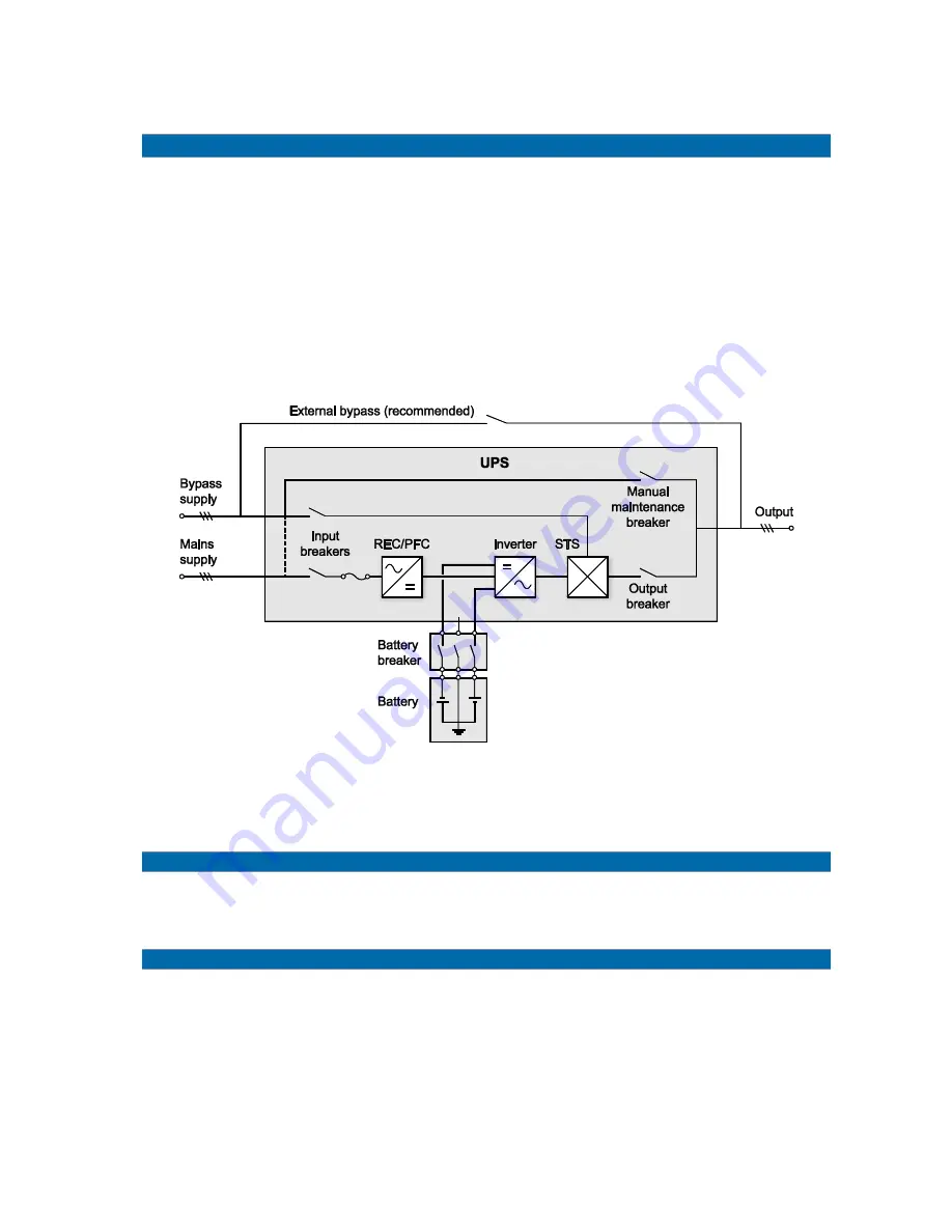
As shown in Figure 1, input mains is converted to d.c., which in turn feeds a d.c./d.c. battery charger and
an inverter. The inverter then converts the battery voltage to a clean a.c. source, output-independent of
the input. The battery powers the load through the inverter in case of an input mains power failure.
If the inverter is unable to supply power for any reason the load is supplied via the bypass circuit, which
includes the bypass input breaker and the static transfer switch (STS).
If maintenance or repair is necessary the UPS can supply the load via the internal and manually
controlled maintenance bypass breaker. With the exception of the maintenance bypass breakers (internal
and external) all the breakers shown are closed during normal UPS operation.
Figure 1 Single unit block diagram
An external bypass breaker enables a UPS to be replaced without interrupting the load and is
recommended in most installations.
Split bypass input
Figure 1
shows the UPS in what is known as the ‘split bypass’ configuration, in which a separate input
supply (the bypass supply) feeds the internal bypass circuits instead of the mains supply. In this
configuration the link (dotted line) between mains and bypass supply is removed.
Static transfer switch
The static transfer switch (STS) is a power-electronic circuit. During normal operation the load is supplied
via the inverter, however in the event of a UPS overload or inverter failure, the STS transfers the load
automatically to the bypass circuit. To provide a clean (no-break) load transfer between the inverter
output and bypass line, the inverter output is synchronized to the bypass supply during normal operating
conditions.


