4.
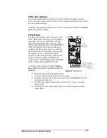
Take note of the driver’s orientation.
5.
Carefully remove the driver from the display board. Use an even amount of
force to prevent any damage due to bending of the connector pins on the
display board.
Reverse the previous steps to replace the driver.
4.5 Power
Supply
Reference Drawing:
Schematic .................................................................
Refer to Appendix C
Note: Disconnect power from the display before removing a power supply
.
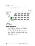
The power supply is mounted behind every other module. The first power supply is
located behind module A102. This unit supplies power to the modules A101, A102,
A201, and A202. The remaining power supplies are located behind A103, A105,
A107, and A109, when applicable. One power supply connects to four (4) modules
(refer to
schematics
).
Refer to
Section
for information on removing a module. Once the module has
been removed from the display:
Tools needed: 8mm Allen wrench, 5/16"
nutdriver, and #2 Phillips screwdriver
1. Open the display and remove the module directing in front of the failed
power supply.
2.
Disconnect the wires from the terminal block at the bottom of the power
supply. It helps to have the wires labeled for reconnecting them to the
power supply.
3.
Use a Philips screwdriver to remove the power supply and bracket from the
vertical support.
4.
Remove the screws securing the power supply to the bracket.
5.
Attach the new power supply to the bracket using M4x8mm screws.
6.
Attach the power supply/bracket assembly to the vertical support with #6
screws and washers.
7.
Reconnect all wires to the power supply as shown in
schematics
.
Maintenance and Troubleshooting
4-3


