background image

Fiber Interconnection 

A four-conductor fiber cable is used in connecting two or more displays in the Fiber 
Interconnection method. Connect the fiber cable to the fiber cards of the display as 
described on the following: 


Sign A 

Data Out (J2 and J3) 

Field 

Cabling 

Sign B 

Data In (J4 and J5) 

J2 (TX1) 

J5 (RX2) 

J3 (RX1) 

J4 (TX2) 

3.8 Initial Operation 

When first operated, the display will run through an initialization in which it will 
display the following: 


1. 

Output Test (DDDs) 

2. 

Product Name (Galaxy) 

3. 

Display Size (Row x Column) 

4. 

Firmware Number (

ED10134

5. 

Firmware Revision (Rev X.XX) 

6. 

COM1 Configuration (C1: V15/RTD) 

7. 

COM2 Configuration (C2: None) 

8. 

Line Frequency (60 Hz) 

9. 

Hardware Address (HW: XX) 

10. 

Software Address (SW: XX) 

11. 

Display Name 

12. 

Modem (if Present)

Electrical Installation


3-13


Summary of Contents for Galaxy Series

Page 1: ...axy Series AF 3010 Display Manual ED 10972 Rev 9 12 August 2003 331 32nd PO Box 5128 Brookings SD 57006 Tel 605 697 4034 or 877 605 1113 Fax 605 697 4444 www daktronics com email helpdesk daktronics c...

Page 2: ...ity for errors or omissions No part of this book covered by the copyrights hereon may be reproduced or copied in any form or by any means graphic electronic or mechanical including photocopying taping...

Page 3: ...e Cover Page uses the front of the page blank on back Section heading pages always start on a new page they never start on the back of another page 3 Drawings included in this manual are located withi...

Page 4: ......

Page 5: ...tion Overview 2 1 2 2 Support Structure Design 2 1 2 3 Display Ventilation Requirements 2 2 2 4 Mounting Kit 2 2 2 5 Display Lifting 2 2 2 6 Display Cabinet Mounting 2 3 Wall Mount 2 3 Pole Mount 2 3...

Page 6: ...Accessing and Replacing the Controller Board 4 4 LEDs and Jumpers 4 4 Controller Address and Test Mode 4 5 Light Detector 4 6 4 7 Transformer 4 6 4 8 Modem 4 6 Accessing and Replacing the Modem 4 6 LE...

Page 7: ...Figure 15 Flipped Cable with RJ Connectors 3 3 Figure 16 Installation with Ground and Neutral Conductors Provided 3 4 Figure 17 Installation with Only Neutral Conductor Provided 3 5 Figure 18 RS232 Co...

Page 8: ...l Routing 4 8 Figure 34 Temperature Sensor Eave Wall Mount A 1 Figure 35 Temperature Sensor Mounting to Bottom of Display A 1 Figure 36 Temperature Sensor Connection and Interconnection A 3 Figure 37...

Page 9: ...sses such things as removing basic sign components troubleshooting the sign performing general maintenance and exchanging sign components Appendix A offers general information about the optional tempe...

Page 10: ...and require little maintenance However from time to time certain sign components will need replacing The Replacement Parts List in Section 4 13 provides the names and part numbers of components that...

Page 11: ...ulty Daktronics decided to use the very popular and readily available RJ11 connector This connector is also used on modern home and office telephone equipment All that is required for signal installat...

Page 12: ...lient Radio connected to the display Refer to Section 3 and the radio manual ED 13932 for additional information 1 4 Display Overview Reference Drawing Shop Drawing Refer to Appendix C The Daktronics...

Page 13: ...sionally alters standard design to meet customer needs the actual sign design may vary slightly from the illustrations below This is only a brief overview Refer to Section 4 for more detailed informat...

Page 14: ...lays can exist on one network Pixel Cluster of four LEDs The number and color of the LEDs depends on sign application Power Supply Converts AC line voltage from the load center to low DC voltage for o...

Page 15: ...mmunicate maintenance or troubleshooting efforts Figure 7 Module Numbering A module is the building block of the Galaxy sign Each module measures 8 pixels high by 16 pixels wide By placing modules sid...

Page 16: ...driver board 0A _ _ _ _ _ _ _ _ represents an assembly such as a circuit board and the plate or bracket to which it is mounted A collection of circuit boards working as a single unit may also carry a...

Page 17: ...eyebolts also decreases with the lift angle due the bending stress on the eyebolts In sum the smaller the angle between the cable and the top of the display the lighter the sign must be to safely lift...

Page 18: ...0 91 300 Blank 1 1 2 6 3 17 800 4 500 3 600 A Do not use eyebolts on angular lifts unless absolutely necessary For angular lifts the shoulder pattern eyebolt is preferred B Load should always be appli...

Page 19: ...A qualified individual must make all decisions regarding the mounting of this sign Read both the mechanical and electrical installation sections of this manual before beginning any installation proced...

Page 20: ...When using a Daktronics mounting kit refer to the instructions in Section 2 5 2 5 Display Lifting Reference Drawing Shop Drawing Refer to Appendix C Eyebolts are provided on the top of each display fo...

Page 21: ...69 Wall Mount Note Because each site differs the Daktronics wall mount kit is not a complete installation kit It is the customer s responsibility to determine the proper wall mounting method and locat...

Page 22: ...opening and secure using 1 2 nuts and lock washers 3 Position the display at the front of the beams with the threaded rods extending from the rear of the channels straddling the poles 4 Raise the dis...

Page 23: ...ectors encountered during sign installation and maintenance 1 Ribbon Cable Connectors Figure 10 on the right illustrates a typical ribbon connector To disconnect the ribbon cable push the plastic clip...

Page 24: ...RJ connectors are similar to the telephone connectors found in homes and are used on the ends of RJ11 or RJ45 cable In order to remove this plug from the jack depress the small clip on the underside o...

Page 25: ...Outdoor Radio Gen 2 Drawing A 185325 Shop Drawing Refer to Appendix C Daktronics does not include the conduit Knockouts will be provided for power and signal Separate conduit must be used to route Po...

Page 26: ...nnot be used as an earth ground electrode The support is generally embedded in concrete and if in earth the steel is either primed or it corrodes making it a poor ground Power Installation There are t...

Page 27: ...ctors should be used The neutral and the ground conductors should be bonded in the display power termination panel Refer to Figure 17 below for installation details Figure 17 Installation with Only Ne...

Page 28: ...k up Note The telephone lines must be dedicated lines and not run through a switch board communications system Fiber Optic This cable is a 4 fiber cable Daktronics part number W 1376 Two fibers are us...

Page 29: ...185325 RS232 One end of the signal cable should be terminated to the 10 position terminal block in the display labeled IN RS232 TB42 Drawing A 88427 is an example of the termination panels The opposit...

Page 30: ...r Daktronics part number 0A 1127 0237 Refer to Drawing A 92681 shows an example system riser using the RS422 signal termination Figure 19 RS422 Signal Converter Connections Signal Converter J4 J5 Fiel...

Page 31: ...in 4 N C Pin 5 N C Pin 6 Drawing A 88426 shows an example modem system setup Fiber Optic Route conduit and fiber cable from the PC to the left end of the master display Continue routing fiber to the c...

Page 32: ...er radio The cable must be in conduit when exposed to outdoor conditions The distance from the J box to the Server radio should not exceed 1000 feet Figure 22 on the following page shows the connectio...

Page 33: ...Figure 22 J box to Server Radio Connections Figure 23 Client Radio to Display Connections Electrical Installation 3 11...

Page 34: ...mmon method of terminating signal between two or more signs A 6 conductor cable is used and one end terminates at the OUT RS422 10 position terminal block TB43 on the first display The other end termi...

Page 35: ...5 J2 TX1 J5 RX2 J3 RX1 J4 TX2 3 8 Initial Operation When first operated the display will run through an initialization in which it will display the following 1 Output Test DDDs 2 Product Name Galaxy 3...

Page 36: ......

Page 37: ...ially in windy conditions 4 1 Weather Stripping To ensure that the display is waterproof weather stripping has been provided around the entire display and around the face panel It is important that th...

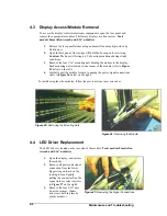
Page 38: ...w on the left 4 Carefully pull the module forward to unplug the power signal connections refer to Figure 26 below on the right To install or replace the modules follow the previous steps in reverse or...

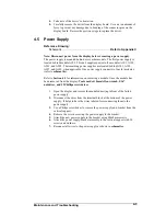
Page 39: ...four 4 modules refer to schematics Refer to Section 4 3 for information on removing a module Once the module has been removed from the display Tools needed 8mm Allen wrench 5 16 nutdriver and 2 Philli...

Page 40: ...all power and signal connections from the board Pressing outward on the tabs and carefully pulling them from the jack releases the Locked connectors 3 Remove the mounting six screws using a 3 16 nutdr...

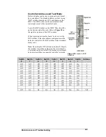
Page 41: ...n as the defective controller The DIP switches follow standard binary code Note By setting the DIP switches to address 0 flip all the switches toward the numbers on the circuit board a test mode can b...

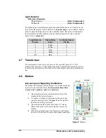
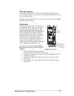
Page 42: ...odem fiber converter or radio depending on the communication method used It is located in the bottom left corner front view of the display in the power termination box 4 8 Modem Figure 31 Modem Access...

Page 43: ...converter In addition the fiberboard has two input fiber connectors that the signal converter or the previous display connects to and two output fiber connectors that connect to the next display The...

Page 44: ...l tie points and ground rods Fasteners should be checked tightened or replaced as required At least once a year check the inside of the display for signs of water intrusion i e water stain marks Water...

Page 45: ...ot working Replace the second driver that isn t working Replace the power supply on the first module on the left side of the module that is not working Replace controller Entire display is garbled Che...

Page 46: ...1 Output Test DDD s 2 Product Name Galaxy 3 Display Size Row x Column 4 Firmware Number ED10134 5 Firmware Revision Rev X XX 6 COM1 Configuration C1 V15 RTD 7 COM2 Configuration C2 None 8 Line Freque...

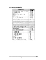
Page 47: ...able Controller to Top Module 0A 1000 0006 Ribbon Cable Between Modules W 1362 Cable RS232 DB9F to DB25M 6 W 1249 Adapter DB9M to DB25F A 1603 Flipped PC Connector DB9F RJ11F Fiber 0A 1146 0029 Cable...

Page 48: ...alleviate confusion when the failed component arrives at Daktronics Daktronics expects immediate return of the exchange part if it does not solve the problem For most equipment you will be invoiced f...

Page 49: ...uld be put in an anti static bag before boxing Please enclose your name address phone number and a clear description of symptoms Mail Daktronics Inc Customer Service PO Box 5128 331 32nd Avenue Brooki...

Page 50: ......

Page 51: ...dings as seen in Figure 34 on the right Due to the nature of the signal cable used to send the temperature information the maximum distance between the temperature sensor and the display is 1 000 feet...

Page 52: ......

Page 53: ...Pin 8 White Temp RX N Pin 9 Red Temp 5V Pin 10 Black Temp GND Pin 10 Bare N A 2V Displays If the display is 2V one temperature sensor is used for both sides An extra piece of the 4 conductor cable mu...

Page 54: ......

Page 55: ...port Serial port or serial cable may be bad OFF Steady Normal state SC is not transmitting data TX Brief Flicker SC is transmitting data ON Steady Field cabling between SC and display is bad connected...

Page 56: ...for a fiber signal converter JACK OPERATION J1 25 Pin DB F J2 TX1 out PIN OPERATION J3 RX1 in 2 TX P out J4 TX2 out 3 RX P in J5 RX2 in 7 GND Loop Back Test To perform a loop back for testing purpose...

Page 57: ...r Diagram Modem Drawing A 88426 System Riser Diagram Power Signal V1500 displays Drawing A 88427 System Riser Diagram RS422 Drawing A 92681 System Riser Diagram RS232 Drawing A 96058 System Riser Diag...

Page 58: ......

Page 59: ......

Page 60: ......

Page 61: ......

Page 62: ......

Page 63: ......

Page 64: ......

Page 65: ......

Page 66: ......

Page 67: ......

Page 68: ......

Page 69: ......

Page 70: ......

Reviews: