


Introduction
3
Remove A Module From The Spare Parts Rack
1�
With one hand on the module face, insert the
1
/
8
" hex
head wrench into the bottom access hole.
2�
Turn the latch release approximately a quarter-turn
counterclockwise. You should feel the module release
from the module bracket.
3�
Disconnect the SATA cables from the back of the
module.
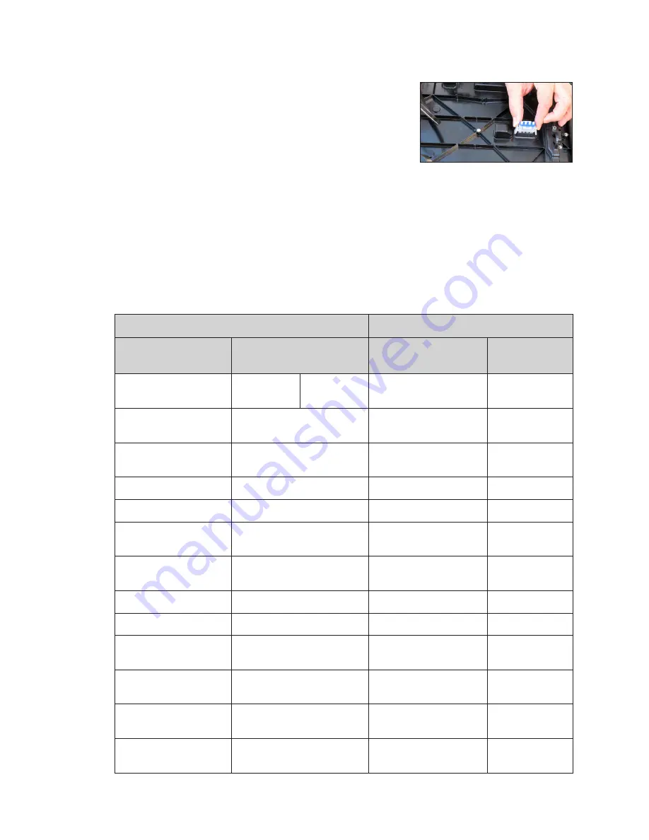
4�
Remove the plug inserted into the power jack, as
shown in
. Store the plug and cable in an area
free of debris for future use with replacement modules.
Field Replaceable Units
The table below lists component names and part numbers of components that can be
replaced in the display and the control system. Some of these components are located
in the spare parts rack. Contact the RSS to order components when needed.
Display FRUs
Control System FRUs
Description
Daktronics Part Number
Description
Daktronics Part
Number
Module
0A-2278-5000
20MT
0A-2277-5000
16MT
Meraki Router
A-4036028
400W Power Supply
0A-2133-4005
DMP-8000 Player
(Market)
0A-2285-0011
Surge Suppressor
A-3732
DMP-8000 Player
(Lamar)
0A-2285-0012
Light Sensor - MDLS
0A-1690-4000
DMP-8000 Player (CCO) 0A-2285-0013
3 Pole Contactor
A-3157
VIP-5160.2
0A-1603-8402
Axial Fan .4 A 115 Volt
B-3505432
Ethernet Switch
(Market)
0A-1853-1200
12 VDC Relay
K-1040
Ethernet Switch (Lamar
and CCO)
A-2249
28" SATA Cable
W-2885
500 W Heater
0A-1690-2900
72" SATA Cable
W-2889
Mobotix Webcam
0A-1853-4605
Line Filter
Z-1007
Mobotix Webcam
(Fisheye Lens)
0A-1604-4646
Term Panel - 20 Amp
Single Pole Breaker
S-1045
SmartLink
TM
(U.S./Can./
Mex)
A-3707
Term Panel - 15 Amp
Breaker
S-1035
SmartLink
TM
(120V
International)
A-3189335
Term Panel - 20 Amp
Two Pole Breaker
S-1126
Temperature Sensor
0A-1151-0013
Figure 5:
Remove Plug From
Power Jack on Spare Module


