Daktronics DB-66 Series Service Manual Download Page 16

Test and Remove Modules

12

6� 

Insert the 

1

/

8

" hex head wrench into the top access hole and turn approximately a 

quarter-turn clockwise or until you feel it latch in place.

7� 

Gently pull on the module to verify it is properly seated.

Remove a Module (Rear Access)

Required Tools:


1

/

8

" hex head wrench, or 

1

/

8

" L-handle hex 

head wrench for modules in the bottom or top rows of a 

section, module lanyard (from the spare parts rack)

1� 

Attach one end of the safety lanyard to a lanyard 

ring on the top of the module.

2� 

Feed the lanyard through the lanyard ring on the top 

of the display directly below the module that will be 

removed.

3� 

Attach the other end of the lanyard to the lanyard 

attachment ring on the bottom of the module that 

will be removed. Refer to 

Figure 12

.

4� 

Disconnect the SATA and power cables from the 

back of the module.

5� 

With a 

1

/

8

"  hex head wrench, turn the bottom latch 

gear approximately a quarter-turn clockwise to 

disengage the latch.

6� 

With a 

1

/

8

" hex head wrench, turn the top latch gear 

approximately a quarter-turn clockwise to disengage 

the latch.

Note: 

Maintain a firm grip on the module as you 

remove it from the face sheet.
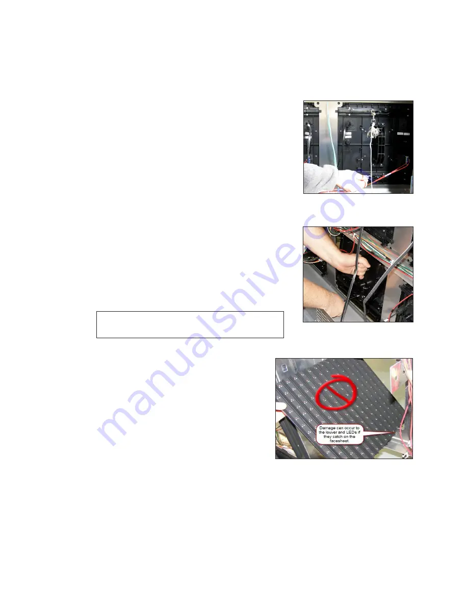
7� 

Rotate the module in a way that allows you 

to guide it through the frame opening without 

catching the louvers or LEDs on the cabinet. 

Figure 13

 shows proper module removal from 

the back. 

Figure 14

 shows improper module 

removal from the back.

Figure 12: 

Attach Safety Lanyard 

to Modules

Figure 13: 

Proper Module 

Removal From Back

Figure 14: 

Improper Module Removal 

From Back

Summary of Contents for DB-66 Series

Page 1: ...201 Daktronics Drive Brookings SD 57006 5128 www daktronics com support 800 325 8766 DB 66XX SERIES DIGITAL BILLBOARD SERVICE MANUAL P2283 DD4816468 Rev 02 04 May 2021...

Page 2: ...limits for a Class A digital device pursuant to part 15 of the FCC Rules These limits are designed to provide reasonable protection against harmful interference when the equipment is operated in a com...

Page 3: ...15 Module Status Indicators 15 Perform a Module Self Test 15 Replace Module Power Supplies 15 Test and Replace a ProLink Router 16 Test a PLR 16 Testing the Display Face with the PLR 16 Replace a Pro...

Page 4: ...ii This page intentionally left blank...

Page 5: ...ule Consists of a display board with LEDs a driver board or logic card housing a module latch assembly and a louver Each module is individually removable from either the front or back of the display M...

Page 6: ...Pin Mate N Lok Plug P 1439 Air Filter EN 2564 Splice Tool TH 1186 400W Power Supply 0A 2133 4005 Locate the Spare Parts Rack Spare parts are located inside the display cabinet behind the left most doo...

Page 7: ...lay FRUs Control System FRUs Description Daktronics Part Number Description Daktronics Part Number Module 0A 2278 5000 20MT 0A 2277 5000 16MT Meraki Router A 4036028 400W Power Supply 0A 2133 4005 DMP...

Page 8: ...tion Daktronics Part Number Power Entrance 15 Amp 1P Breaker S 1187 60 V Surge Protector A 3159 Power Entrance 20 Amp 2P Breaker S 1243 Axial Fan 16 A B 1102 Power Entrance 6 Amp 1P Breaker S 1244 Fil...

Page 9: ...tion panel and is redistributed to the power supplies Refer to the layout drawing for display specific power distribution Display Signal Overview Signal is sent from the DMP 8000 to the VIP 5160 The V...

Page 10: ...ons in the SmartLinkTM to cycle power to the components because it can take as long as an hour to reset the relays Display Troubleshooting Work with Daktronics help desk or experienced technicians to...

Page 11: ...lp desk at 1 877 DAK HELP 325 4357 and have them verify the content that was supposed to play was successfully uploaded and sent to the display Display too bright 1 Immediately call Daktronics help de...

Page 12: ...y the PLR has power and is functioning Disconnect and reconnect power to the PLR 6 Verify there is power to that display section by checking module status indicators on multiple modules If there is no...

Page 13: ...e power indicator is on there is most likely a SATA cable issue If the module power indicator light is off check the power supplies for the modules at each end of the issue are on If not power or sign...

Page 14: ...the door outward so it clears the tab located on the door Refer to Figure 9 3 Lift the door upward to disengage its tabs from the slots on the display s backsheet Refer to Figure 10 4 Lower door unti...

Page 15: ...module from the display face just far enough to reach the back of the module 4 Disconnect the power and SATA cables from the back of the module 5 Gently place the module on a clean and dry surface No...

Page 16: ...ard to the lanyard attachment ring on the bottom of the module that will be removed Refer to Figure 12 4 Disconnect the SATA and power cables from the back of the module 5 With a 1 8 hex head wrench t...

Page 17: ...the enclosure Reinstall a Module Rear Access When installing new modules place them in the outer ring of the display 1 Rotate and carefully guide the module through the module opening as shown in Figu...

Page 18: ...ower harness attached to the fan Refer to Figure 18 2 Press inward on the bottom of each side of the fan plenum Refer to Figure 19 3 When the plenum tabs shown in Figure 20 disengage gently pull the p...

Page 19: ...0 seconds 3 Reconnect the power to start the self test 4 Verify the module is running a self test Remove the SATA cable and cycle power to the module to stop the self test For more information see DD1...

Page 20: ...if the error persists after troubleshooting Note It is possible to have a break in just one path so for example it is possible all of the modules may turn Yellow indicating A is healthy but only some...

Page 21: ...e PLR SATA and power cables 3 Using a Phillips screwdriver loosen the PLR assembly set screw 4 Lift the PLR assembly to disengage it from the display 5 Reverse Steps 2 4 to install the new PLR 6 Verif...

Page 22: ...loss detection and remote power cycling for the DB 66XX series digital billboards Figure 34 shows the SmartLinkTM configuration Open the ISP Box To access ISP box components complete the following st...

Page 23: ...the incoming power to the VIP 5160 2 Disconnect the communication cables 3 Remove the screw at the bottom of the VIP 5160 4 Lift the VIP 5160 and disengage the hooks to remove it 5 Reverse Steps 1 4...

Page 24: ...from the router 2 Disconnect the Cat 5 cables from the side of the router 3 Carefully and firmly pull the router forward off of the dual lock tape and out of the enclosure 4 Reverse Steps 1 3 to inst...

Page 25: ...r Required Tools Phillips screwdriver 1 Unplug the 3 pin Mate N Lok power jack from the outside of the enclosure 2 Disconnect the power cables from both sides of the Z filter 3 Remove the screws that...

Page 26: ...ld dim within a couple of minutes Remove the fabric and verify the display returns to the brighter setting If possible work with the help desk and have them monitor the display IDM dimming levels Repl...

Page 27: ...ee short bolts 5 Work with Daktronics help desk to verify the webcam is focused and functioning properly Troubleshoot the Webcam This section provides some basic power troubleshooting steps to perform...

Page 28: ...SP box is connected and LED indicators are on If the LED indicators on the POE switch are on check the Ethernet connections from the Router to the POE switch from the POE switch to the back of the dis...

Page 29: ...tting it in the enclosure Inspect the control system for damage Perform an inventory of the spare parts rack Have the help desk run a diagnostics check of the display Work with the help desk to repair...

Page 30: ...26 This page intentionally left blank...

Page 31: ...ments in this section Reference Documents Performing a Daktronics Module Self Test DD1944805 How to Perform a PLR 6050 Self Test DD2268420 ProLink Router 6050 Manual DD1735784 Block Diagrams Block Dia...

Page 32: ...28 This page intentionally left blank...

Page 33: ...Daktronics Warranty and Limitation of Liability 29 B Daktronics Warranty and Limitation of Liability Click here to view Warranty and Limitation of Liability information...

Reviews: