


Test and Replace Display Components
16
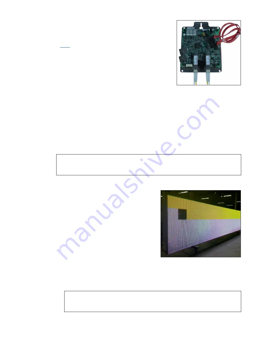
Test and Replace a ProLink Router
A ProLink Router (PLR) sends the signal from the DMP-8000
to the modules via SATA cables.
Click
to view a video about testing and replacing a
ProLink Router.
Test a PLR
Before replacing a PLR, it may be beneficial to perform a
self-test. To perform this test:
1�
Connect a duplex fiber cable from Fiber Port A to
.
2�
Connect a working SATA cable from SATA Port A to
SATA Port B.
3�
Connect the power cable to the PLR. This will start the PLR self-test.
4�
Wait for the test to complete. This may take up to 90 seconds. If the PLR successfully
sends and receives data through each of the ports, the letters P.A.S will appear on
the Seven Segment Display. If the letters E.r.r appear, the Seven Segment Display
will show the port numbers with issues. Refer to the
ProLink Router 6050 Manual
in
Appendix A
for a full list of error codes.
5�
Replace the PLR if the error persists after troubleshooting.
Note:
It is possible to have a break in just one path, so for example it is possible all of
the modules may turn Yellow indicating “A” is healthy, but only some of them
turn Magenta indicating a break in the “B” path that needs to be repaired.
Testing the Display Face with the PLR
1�
Loop a fiber cable across the A and B fiber
ports (ProLink6) on the PLR (SATA cables will be
left connected to modules) and cycle power
to the PLR. The PLR will display the following
content on the portion of the display that the
PLR is controlling:
• Solid Red (signal is sent out of ProLink5
ports A and B).
• Solid Green (signal is sent out of ProLink5
ports A and B).
• Solid Blue (signal is sent out of ProLink5
ports A and B).
• Solid White (signal is sent out of ProLink5
ports A and B).
• Solid Amber (signal is only sent out of ProLink5 port A).
Note:
Any modules that show white while on this test indicate a break in the
signal path. If all of the modules turn yellow, it indicates the signal path in
the “A” direction is working 100 percent. Refer to
.
Figure 24:
ProLink Router
Connected For Self-Test
Figure 25:
ProLink Router Port A Test


