background image


2-6 

Transponder Interface Operation 


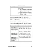
Blank with 1st Position 


LCD Display 

Action 


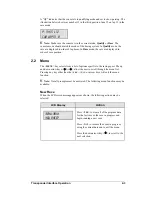
BLANK ALL WHEN  
1ST POS RCVD? N* 

 
*

 = current setting (Y/N) 


Press <

YES

>


yes to blank all positions (other 

than first place) when a first-place time is 
received from the transponder. 


All other positions will be displayed as they 
cross the loop. 


K


Note:

 This setting is 

NOT

 applicable if 

the console is in 

Qualify

 mode 

AND

 set to 

show passing information. 


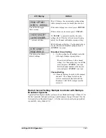
Show Passing Lap Time 


LCD Display 

Action 


SHOW PASSING LAP  
TIME INFO? N* 


*

 = current setting (Y/N) 


Press 

<

YES

>


to show lap time information on 

the lap time section of the scoreboard when 
passing information is received from the 
transponder. 


K

 Note:

 Passing information will only be 

displayed if the console is in 

Qualify

 mode. 

This information will be displayed in the 
"Current Competitor" RTD item numbers and 
on fixed-digit, or numeric, time displays. For 
a more detailed explanation, refer to the All 
Sport 5100 Enhanced RTD item numbers in 

Appendix D.


Summary of Contents for All Sport 5100

Page 1: ...All Sport 5100 Timer Operations Manual ED 12501 Rev 8 02 December 2003 ...

Page 2: ......

Page 3: ...ronic or mechanical including photocopying taping or information storage and retrieval systems without written permission of the publisher All Sport Chrondek CompuLink TM PanaView Venus are trademarks of Daktronics Inc Windows is a registered trademark of its owner Please fill in the information below for your display use it for reference when calling Daktronics for assistance Display Serial No __...

Page 4: ...A 125290 A 180521 A 139243 A 180566 A 139244 A 180922 A 139347 A 180923 A 139399 A 181729 A 143444 A 195690 A 143453 B Drawings B 123256 B 145382 B 139666 B 145433 B 144445 B 164173 4 Materials to be inserted in this manual include the following Note 1 Appendices B C D E F and H are permanent and materials are in place Note 2 In Appendix G Sport Code Labels insert All Sport 5000 Sport Code Labels ...

Page 5: ...t Systems 1 11 Section 2 Transponder Interface Operation 2 1 2 1 Transponder Interface Overview and Operation 2 1 Basic Operation for Transponder Interface 2 2 2 2 Menu 2 3 New Race 2 3 New Code 2 4 Race Qualify Mode 2 5 2 3 Edit Settings 2 5 Blank with 1st Position 2 6 Show Passing Lap Time 2 6 Show First Pass 2 7 Starting Position Displayed 2 7 Maximum Position Displayed 2 8 Position Display Tim...

Page 6: ... Keys 4 2 Red Yellow Green Status 4 3 Black Flag 4 3 Display Black Flag 4 3 Reset 4 3 Display Best Lap Time 4 3 Display Running Time 4 3 Display Time of Day 4 3 Set Time 4 4 Start Enable Lap Enable Stop Enable 4 4 Laps 4 4 4 3 Lane Track Timing Keys 4 5 Start 4 5 Stop 4 5 Reset 4 5 4 4 Menu 4 5 New Race 4 5 New Code 4 6 Dimming Level 4 6 Separate Photocell Lanes 4 7 Time of Day 4 7 4 5 Photocell T...

Page 7: ...s 5 9 Section 6 Track Timing 6 1 6 1 Track Keys 6 2 Reset 6 2 Lane Mode 6 2 Place Mode 6 3 Non Lane Mode 6 3 Home and Guest 1 2 and 3 Score 6 3 Event and Heat 6 4 Lane ON OFF 6 4 Lane Status 6 4 Lane Place Order 6 4 Edit6 4 6 2 Menu 6 4 New Game 6 5 New Code 6 5 Dim6 5 Home Roster Guest Roster 6 6 Display Menu 6 6 Edit Settings 6 7 Time of Day 6 7 6 3 Settings 6 8 Guest 2 and Guest 3 6 8 Lanes Use...

Page 8: ... Software Information 8 1 RentiX Settings 8 1 ChronX Settings 8 2 8 3 Troubleshooting 8 2 Appendix A Reference Drawings A 1 Appendix B Transponder Reference Materials B 1 Appendix C All Sport 5100 C 1 Appendix D All Sport 5100 Racing RTD Items D 1 Appendix E Daktronics Racing Display Protocol E 1 Appendix F Rmonitor Supported Protocol Packets F 1 Appendix G Sport Code Labels G 1 Appendix H All Spo...

Page 9: ... the Daktronics drawing numbering system The drawing number is located in the lower right corner of the drawing label in the example 7087 P08A 69945 Drawings in this manual are referenced by their last set of digits and the letter preceding them In Figure 1 the drawing would be referred to as Drawing A 69945 Drawings are grouped and inserted in alphanumerical order in Appendix A 1 2 Introduction T...

Page 10: ... 5100 is backlit to provide optimum viewing of current event information even in low light areas and an audible beep sounds to indicate when a command has been received Operation of the All Sport 5100 is simple The user enters a four digit code on power up to indicate the operating mode for the race Basic choices include Manual mode which uses infrared photocells for timing or Automatic mode with ...

Page 11: ...onsists of a two line by 16 character LCD screen sport specific keyboard insert numeric keypad operation keys main clock keys and LEDs for status Throughout this manual the names or letters of keys on the keyboard are enclosed in angle brackets such as ENTER All of the keys pertaining to a specific sport code insert are explained in detail in the section of the manual devoted to that specific appl...

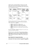
Page 12: ...control the display as specified by the keys on the insert The following table lists the codes available Code Mode of Operation Displays Insert 300 Photocell All Sport 5100 Console Only Oval track photocell code CHTS 300 replacement 0G 139347 301 Transponder interface CH 2001 CH 2002 CH 700 positions 1 12 0G 139243 303 Photocell All Sport 5100 Console Only Lane track photocell code CHTS 300 replac...

Page 13: ...a dot The additional information required is usually a number followed by the ENTER key Some keys contain a 1 symbol Pressing one of these keys once increments increases the value of the corresponding field by one A key with a 1 symbol decrements decreases by one Certain keys have been grouped together under the heading Manual These keys in addition to the keys used in transponder mode are used on...

Page 14: ...n memory The console is now ready for operation Press NO to start a new event or change to a different sport The console will prompt for a new code number as shown below SELECT CODE CODE nnnn nnnn last code selected The Select Code prompt allows you to accept the last code selected displayed on the second line or enter a new code To accept the code shown press ENTER To select a new sport code 1 Ge...

Page 15: ...e broadcast channel of its respective broadcast group This is selected by setting the transmitter console radio to channel 0 Every radio receiver will also accept data sent from the Master Broadcast channel This is selected when a transmitter console radio is set to Broadcast Group 0 BCAST 0 and Channel 0 The channel number and broadcast group set on the radio installed in each scoreboard can be v...

Page 16: ...ally detect when a radio transmitter is installed and will prompt the user for transmitter settings The All Sport Console will show the current transmitter radio status on the LCD when a code is entered An overview of radio settings is shown below LCD Display Action The LCD will toggle these screens current edit item The bottom line shows the current setting The default setting is Broadcast 1 Chan...

Page 17: ...ystem press CLEAR at the RADIO SETTINGS prompt to change the channel number Typically all Multiple Controller systems will use channel 1 for the first controller All other controllers will use sequential channel settings 2 8 LCD Display Action The LCD will toggle these screens The bottom line shows default settings RADIO SETTINGS BCAST Y CHAN XX Enter to accept clear to modify bcast group 1 radio ...

Page 18: ...cast 2 BCAST2 jumper must be removed Radio Channel Setting Multiple Controller with Single Broadcast Group Typically all multi controller systems will use Broadcast 1 and Channel 1 for the first controller and Channels 2 8 for all remaining controllers All radio receivers must be set with a switch setting corresponding to the console controlling the scoreboard and a Broadcast 1 BCAST 1 jumper set ...

Page 19: ...ress ENTER to accept Broadcast Group Setting 1 Use this setting for all multiple controller with single broadcast group setups The asterisk will move to the channel setting Use the number keys to edit this value and press ENTER to accept Edit the channel number to the desired value and press ENTER to accept Channel Setting 1 8 Channels that may be used with broadcast channel 1 The channel switch o...

Page 20: ...LCD at the left is shown allowing edit of the Channel or Broadcast group setting Edit the Broadcast Setting Use the number keys to enter the desired broadcast group and press ENTER to accept Broadcast Group Setting 0 Master Group All receivers 1 Broadcast Group 1 2 Broadcast Group 2 The asterisk will move to the channel setting Use the number keys to edit this value and press ENTER to accept Edit ...

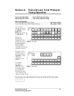
Page 21: ...de Code 300 is for All Sport 5100 consoles only If you do not know the code number for your scoreboard refer to Appendix I in this manual If you do not know the model number of your scoreboard refer to the installation and maintenance manual provided with the scoreboard 2 1 Transponder Interface Overview and Operation Reference Drawings Oval Track Timing System Layout Drawing B 139666 Insert A S 5...

Page 22: ...in numerical order in Appendix B SL03639 Transponder Feed to Daktronics Pylon SL03640 Transponder Feed to Daktronics LED Scoreboard SL03641 Transponder Feed to Daktronics Matrix Scoreboard SL04016 Transponder Feed to Daktronics Incandescent Fixed Digit Scoreboard SL04213 Transponder Feed to Daktronics Matrix and Fixed Digit Time Scoreboard Refer to Drawing B 139666 in Appendix A for information on...

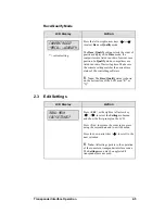
Page 23: ... The MENU key selects from a list of options specific to the racing sport The up and down arrow keys allow the user to scroll through the menu list Pressing any key other than the YES NO or arrow keys will exit the menu function K Note Not all prompts must be answered The following menu functions may be available New Race When the LCD screen message appears as shown the following actions may be se...

Page 24: ... the down arrow key to scroll to the next selection MENU Dimming level 0 9 nn nn current level None bright 0 90 1 80 2 70 3 60 4 50 5 40 6 30 7 20 8 10 9 Press 0 through 9 or use the left or right arrow keys to select the intensity for the digits on the scoreboard Press NO to resume the game in progress using the current data and exit the Menu Press the down arrow key to scroll to the next selecti...

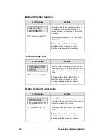
Page 25: ...tting matches the current race status of the controlling software K Note The Race Qualify status is shown on the bottom line of the LCD as an R or Q 2 3 Edit Settings LCD Display Action MENU MAIN EDIT SETTINGS Press YES or the right or left arrow key to select the Settings submenu and show the first prompt on the LCD Press NO to resume the event in progress using the current data and to exit the m...

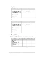
Page 26: ...mode AND set to show passing information Show Passing Lap Time LCD Display Action SHOW PASSING LAP TIME INFO N current setting Y N Press YES to show lap time information on the lap time section of the scoreboard when passing information is received from the transponder K Note Passing information will only be displayed if the console is in Qualify mode This information will be displayed in the Curr...

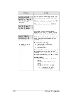
Page 27: ...et the console to disregard the first pass by selecting NO Otherwise if you want the display to update on the first pass of a competitor select YES K Note Passing information will only be displayed if the console is in Qualify mode Starting Position Displayed LCD Display Action START POSITION DISPLAYED nn nn current setting Y N This setting selects the starting position to be displayed in the vari...

Page 28: ...SITION DISPLAY TIME nn nn current setting Y N Enter the time in seconds for each position group to be displayed on the numeric or fixed digit scoreboard before moving to the next group K Note Disregard this setting if your installation does not include a display showing variable position car numbers Restart Position Display Cycle LCD Display Action Restart cycle At start pos N N current setting Y ...

Page 29: ...d status light on the scoreboard YELLOW turns on the yellow status light on the scoreboard GREEN turns on the green status light on the scoreboard K Note If status is available the controller will automatically take the status information from the transponder interface If this is the case status received from the interface will override the selected status Black Flag LCD Display Action BLACK FLAG ...

Page 30: ...lap number by one Current Lap Time LCD Display Action P nn xxx L yyy T HH MM SS DCM nn current position xx car number yy lap number HH MM SS DCM current lap time Enter the value of the current lap time to be displayed on the scoreboard K Note This time will be displayed in the current time position on the scoreboard To set individual lap times use the TIME key Car Number LCD Display Action P nn xx...

Page 31: ...n hh mm ss Dcm nn current position xx car number yy lap number hh MM SS DCM current lap time Enter the new lap time for the selected position and press ENTER 2 6 Default Settings Write the settings for this installation in the spaces Custom 1 2 and 3 provided Setting Default Custom 1 Custom 2 Custom 3 Race Qualify Mode Race Blank on 1st Position No Show Passing Lap Times No Start Position for Vari...

Page 32: ...ion Continued from previous page Setting Default Custom 1 Custom 2 Custom 3 Max Position for Variable Position Pylon 45 Cycle Time for Variable Position Pylon 3 seconds Restart when Starting Position Received Variable Position Pylon No ...

Page 33: ...dered Use the labels provided in Appendix G to attach the correct code number label at the appropriate location on the sport insert Write the code number in the boxes below Sport Insert Code If you do not know the code number for your scoreboard refer to Appendix I in this manual If you do not know the model number of your scoreboard refer to the installation and maintenance manual provided with t...

Page 34: ...the scoreboard Display Laps DISPLAY LAPS displays the current lap number on the scoreboard Display Time DISPLAT TIME displays the time elapsed on the scoreboard Count Up Down LCD Display Action Main clock up 1 up 2 down COUNT UP sets the main clock to count up or down Press 1 or 2 and ENTER to change count modes The controller LCD displays an up arrow if the clock is counting up and a down arrow i...

Page 35: ...be used to quickly enter the car numbers displayed for a series of race positions LCD Display Action POSITION 1 POSITION y CAR nn nn current car number for position y Press ENTER to start editing car numbers with position 1 Press the number keys to change the starting position to be edited Enter the new car number for the specified position and press ENTER The LCD will display the next position fo...

Page 36: ......

Page 37: ...erence is located in Appendix H Refer to the information in Sections 1 5 1 8 to start the console and to use the sport insert Read the material carefully to fully understand the following operating instructions If an insert is lost or damaged a copy of the insert drawing in Appendix A can be used until a replacement can be ordered Use the labels provided in Appendix G to attach the correct code nu...

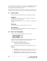
Page 38: ...ace keys to enter the car number for places 1 10 Reset All Places Press RESET ALL PLACES and ENTER to clear all place numbers from the display and from the console memory 4 2 Oval Track Timing Keys The LCD view below shows the main menu for the oval track codes mm ss tht START PCELL I ENABLE The current time is shown in the upper left portion of the LCD This time may be running time or lap time de...

Page 39: ... is being black flagged Display Black Flag DISPLAY BLACK FLAG displays on the scoreboard the number of the car that was black flagged This number will flash when displayed on the scoreboard Reset Press RESET to reset the race timer If the timer is currently running the console will wait for an ENTER keypress to confirm the reset Pressing the RESET key also clears the Best Lap Time in preparation f...

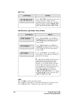
Page 40: ... timer will be stopped the next time the photocell beam is broken Press LAP ENABLE and ENTER to set the console to record a lap time with the next photocell beam crossing K Note Photocell inputs will only be active when enabled for start stop or lap If the photocell is not enabled for one of these functions a car crossing the photocell beam will not affect the timer status After a lap enabled phot...

Page 41: ...perate either separately or together based on the Separate Lanes setting Start Press START to manually start the photocell timer Stop Press STOP to manually stop the photocell timer Reset Press RESET to reset the race timer If the timer is currently running the console will wait for an ENTER keypress to confirm the reset 4 4 Menu The MENU key allows the user to select from a list of options specif...

Page 42: ...n Dimming Level LCD Display Action MENU Dimming level 0 9 nn nn current level None bright 0 90 1 80 2 70 3 60 4 50 5 40 6 30 7 20 8 10 9 Press 0 through 9 or use the left or right arrow keys to select the intensity for the digits on the scoreboard Press NO to resume the game in progress using the current data and exit the Menu Press the down arrow key to scroll to the next selection Note Dim level...

Page 43: ...k setup is used Press the down arrow key to scroll to the next selection K Note This setting will only appear if the operator selects Lane Track Timing mode Time of Day LCD Display Action MENU TIME OF DAY 1 12 2 24 HOUR Press 1 or 2 to display the Time of Day in 12 hour default or 24 hour format Press ENTER or the down arrow key to scroll to the next section MENU TIME OF DAY TOD HH MM SS HH MM SS ...

Page 44: ... information on multiple lane track timing Photocell Inputs Use the XLR connectors on the rear plate of the photocell interface when there are no J box connections at the track or for a portable installation Plug the individual lane start and stop photocells into the rear panel XLR connectors as labeled Any of the Lane 1 or Lane 2 photocell inputs may be used with the oval track photocell timing c...

Page 45: ...he labels provided in Appendix G to attach the correct code number label at the appropriate location on the sport insert Write the code number in the boxes below Sport Insert Code Codes 310 311 and 320 are for the All Sport 5100 console only If you do not know the code number for your scoreboard refer to Appendix I in this manual If you do not know the model number of your scoreboard refer to the ...

Page 46: ...l start inputs to start the timer for each lane These keys would typically be used only for testing the timer operation K Note If the operator presses a START TIMER key after the timer is stopped the timer will be reset to 0 00 before restarting Stop timer STOP TIMER 1 STOP TIMER 2 STOP TIMER 3 and STOP TIMER 4 keys stop their respective timers These keys can be used with or instead of photocell s...

Page 47: ...sage Select the lane number 1 4 and press ENTER to reset that lane K Note This message will only display in Water Slide mode Timer Photocell Status LCD Display Action Pcell status n Start I Stop i N selected timer photocell Pressing the TIMER 1 PHOTOCELL STATUS TIMER 2 PHOTOCELL STATUS TIMER 3 PHOTOCELL STATUS or TIMER 4 PHOTOCELL STATUS displays the status of the selected timer start and stop pho...

Page 48: ... for all races or each race based on the Select Best Time setting See the Select Best Time setting in Section 5 4 D Q Lane Lane Timing Mode Only LCD Display Action disqualify select lane 1 disqualify 1 on 2 off Pressing the DQ LANE key will first prompt for the lane to disqualify Enter the lane number and press ENTER The console will prompt to set the DQ status for the lane On or Off Press 1 to se...

Page 49: ...ata for the last race or the race in progress and begin running the selected sport Press NO to resume the race in progress using the current data and to exit the menu Press the down arrow key to scroll to the next selection New Code LCD Display Action Menu main New code Press YES to begin selection of a new code from the Enter Code prompt clear all of the program data for the last race or the race...

Page 50: ...l of dimming at 50 Edit Settings LCD Display Action Menu main Edit settings Press YES to select the Settings submenu and show the first prompt on the LCD Press NO to resume the event in progress using the current data and to exit the menu Press the down arrow key to scroll to the next selection 5 4 Settings The following settings can be edited by the user when he or she selects Edit Settings from ...

Page 51: ...l break K Note Setting the Photocell Arming Time to 0 will set the stop photocell to be constantly armed Reset Clock Time LCD Display Action Reset clock Time 0 00 The Reset Clock Time setting will cause the timer to reset when it reaches the reset clock value The Water Slide mode will reset individual timers and the Lane Timer mode will reset all timers when one timer reaches the value This settin...

Page 52: ...ing mode 1 1st to finish 1 1st to Finish 2 Best Time Enter the desired Timing mode to select how the lane times are ranked Press 1 ENTER to select 1st to Finish The official timer values will be ranked by the order of finish This is the common Start mode Press 2 ENTER to select Best Time The official timer values will be ranked by the best time order Timer Precision LCD Display Action Timer precis...

Page 53: ...r Best Time selection Press 1 ENTER to select a Best Time each run Press 2 ENTER to select an Overall Best Time from all races Default Settings Write the settings for this installation in the spaces Custom provided Setting Default Custom 1 Custom 2 Custom 3 Arming Delay 0 Reset Clock Time 0 Hold Time 0 Timing Mode First to finish Timer Precision Thousandths Best Time Selection Overall ...

Page 54: ......

Page 55: ...drawing is located in Appendix A The Quick Start Reference is located in Appendix H Refer to the information in Section 1 5 1 8 to start the console and to use the sport insert Read the material carefully to fully understand the following operating instructions If an insert is lost or damaged a copy of the insert drawing in Appendix A can be used until a replacement is ordered LCD in LANE MODE E 1...

Page 56: ...e finish times if all of the lanes have not finished The RESET function will detect a start input that occurred before the reset was done and ask if that start should be used This is the Always Ready Start feature Press YES to accept this start Press NO to ignore this start input Lane Mode LCD Display Action select mode LANE y n Press LANE MODE to set the console to the Lane Mode of operation Pres...

Page 57: ...console to the Non Lane Mode of operation Press YES to accept Non Lane Mode Press NO to abort the mode selection In Non Lane Mode only timing input from Lane 1 will be used to register times Each input on Lane 1 will save a time for a new place The timer will save up to 50 places Home and Guest 1 2 and 3 Score The Home and Guest 1 2 3 Score keys are used to modify the value of home or guest team s...

Page 58: ...e the lane number whose status is shown on the LCD Lane Place Order This key changes the LCD to display the place number of Lanes 1 through 8 The place numbers display on the LCDs bottom line A dash displays if not yet finished and a small o will display if the lane is OFF Edit The EDIT key allows you to edit the time for a lane LCD Display Action Time edit lane n N lane number Time edit lane 1 12...

Page 59: ...prompt Press NO to resume the game in progress using the current data and exit the Menu Press the down arrow key to scroll to the next selection Dim LCD Display Action MENU Dimming level 0 9 nn nn current level None bright 0 90 1 80 2 70 3 60 4 50 5 40 6 30 7 20 8 10 9 Press 0 through 9 or use the left or right arrow keys to select the intensity for the digits on the scoreboard Press NO to resume ...

Page 60: ...lled to enter the Team Name Message Center TNMC settings The TNMC is updated after each selection is completed Use the COLUMNS ROWS and STROKE keys to select the WIDTH HEIGHT and FONT of the TNMC The defaults are 48 columns 8 rows and single stroke Enter up to fifteen 15 characters for the team name and press ENTER Reinstall the TRACK TIMING LL 2587 insert to continue Display Menu The DISPLAY MENU...

Page 61: ...submenu and show the first prompt on the LCD Press NO to resume the game in progress using the current data and exit the Menu Press the down arrow key to scroll to the next selection Time of Day LCD Display Action MENU MAIN SELECT TOD Press YES or the right arrow key to select the Time of Day submenu and show the first prompt on the LCD Press NO to resume the game in progress using the current dat...

Page 62: ... DATA If 2 tod is selected this message will be displayed Press ENTER to blank all game data on the scoreboard except for the Time of Day digits 6 2 Settings You may edit the following settings when EDIT SETTINGS has been selected from the Main Menu Guest 2 and Guest 3 LCD Display Action GUEST 2 3 VALUE SCORE EVNT HT This setting determines the function of the Guest 2 and Guest 3 keys When the val...

Page 63: ...edths or 2 for tenths and then press ENTER Cycle Hold Time LCD Display Action display hold time nn NN hold time in seconds This setting selects the amount of time that each lane s information is displayed on the single line display Enter the time and press ENTER Default Settings Write the settings for this installation in the space Custom provided Setting Default Custom 1 Custom 2 Custom 3 Guest 2...

Page 64: ......

Page 65: ...nd the following operating instructions If an insert is lost or damaged a copy of the insert drawing in Appendix A can be used until a replacement is ordered Use the labels provided in Appendix G to attach the correct code number label at the appropriate location on the sport insert Write the code number in the boxes below Sport Insert Code If you do not know the code number for your scoreboard re...

Page 66: ...3 4 5 0x03 The data below will show 56789 on the bottom right display 0x01 D 4 5 6 7 8 9 0x03 7 2 Chrondek C 33 Portatree Interface Reference Drawing Insert Drag Racing Interface Drawing A 164750 SYSTEM RISER DIAGRAM PORTATREE INTERFACEDrawing A 196027 The All Sport 5100 code for the Chrondek C 33 Portatree Interface is 556 The console receives signal input from the Chrondek C 33 computer or Porta...

Page 67: ...st Mode Reference Drawing Insert CompuLink Interface Drawing A 164750 The console has built in test functions for the data input and the scoreboard output These tests will help isolate system problems and verify proper operation To test the scoreboard output press the ALL ON test and the NUMBER TEST keys When pressed these keys will put the specified pattern on the scoreboard To test the data inpu...

Page 68: ...nds data that will display on the both lines of the right lane display Data Posting Keys LCD Display Action t 12345 t b b TOP LEFT allows the operator to enter a number for display on the top left display t t b 12345 b BOTTOM LEFT allows the operator to enter a number for display on the bottom left display t t 12345 b b TOP RIGHT allows the operator to enter a number for display on the top right d...

Page 69: ...e last race or the race in progress and begin running the selected sport Press NO to resume the race in progress using the current data and to exit the menu Press the down arrow key to scroll to the next selection New Code LCD Display Action Menu main New code Press YES to begin selection of a new code from the Enter Code prompt clear all of the program data for the last race or the race in progre...

Page 70: ...ow key to scroll to the next selection Note Dim levels pertain to outdoor LED products Incandescent and indoor LED products only support one level of dimming at 50 Cycle Time LCD Display Action cycle time tenths 30 This function allows the cycle time of single line displays to be set from 1 0 to 9 9 seconds Press YES to accept the change and move on to the next menu item Press the down arrow key t...

Page 71: ...ceived on the serial port pins 2 7 of J6 on the bottom line of the LCD Press YES to view the data being received Press YES again to end the monitor session and move on to the next menu selection Press the down arrow key to scroll to the next selection Press NO to resume the event in progress using the current data and to exit the menu ...

Page 72: ......

Page 73: ...nformation in Section 6 2 below 8 2 Transponder Software Information Transponder interface codes are used to interface to transponder software such as RentiX or ChronX version 2 0 or later which provide Daktronics racing protocol For a detailed description of Daktronics racing protocol refer to ED 11009 The information listed below details the software specific settings that can be used to configu...

Page 74: ...s initially connected to the computer For ChronX Release 2 0 5 or earlier in order to display driver information on a matrix the competitor registration number must be the same as the car number or not specified This is an issue that will be corrected in later ChronX versions 8 3 Troubleshooting Symptom Condition Possible Cause Corrective Action Fixed digit display is not updating Make sure the tr...

Page 75: ...Also check the transponder software communication settings see Section 6 2 Transponder Software Information immediately preceding this table If position data is received check connections between the All Sport 5100 and display Display information is incorrect Restart the All Sport 5100 using the MENU NEW RACE option This will blank the scoreboard Follow the procedure in the Transponder Settings se...

Page 76: ......

Page 77: ...V Drawing A 180923 Indoor LED Driver Update For Gen IV Radio Receiver Drawing A 181729 Insert LL2587 A S5000 Track Timing Drawing A 195690 B Drawings Cables AMB Interface Drawing B 123256 Oval Track Timing System Layout Drawing B 139666 Permanent Lane Track Timing System Layout Drawing B 144445 Retroreflective Lane Track Timing System Layout Drawing B 145382 Portable Lane Track Timing System Layou...

Page 78: ... Timer Waterslide Drawing A 143770 Lane Track Timing System Layout Drawing B 144445 Retroreflective Lane Track Timing System Layout Drawing B 145382 Portable Lane Track Timing System Layout Drawing B 145433 Section 6 Track Timing Interface Insert LL2587 A S5000 Track Timing Drawing A 195690 Insert A S Team Name Drawing A 125290 Block Diagrams A S5000 3000 Outdoor Sports Drawing A 124690 Section 7 ...

Page 79: ......

Page 80: ......

Page 81: ......

Page 82: ......

Page 83: ......

Page 84: ......

Page 85: ......

Page 86: ......

Page 87: ......

Page 88: ......

Page 89: ......

Page 90: ......

Page 91: ......

Page 92: ......

Page 93: ......

Page 94: ......

Page 95: ......

Page 96: ......

Page 97: ......

Page 98: ......

Page 99: ......

Page 100: ......

Page 101: ......

Page 102: ......

Page 103: ......

Page 104: ......

Page 105: ... to Daktronics Pylon Scoreboard SL03639 MotorsportsTransponder Feed to Daktronics Go Kart LED Scoreboard SL03640 Transponder Feed to Daktronics Matrix Scoreboard SL03641 Transponder Feed to Daktronics Numeric Scoreboard SL04016 Transponder Feed to Daktronics Car Number Numeric Scoreboard SL04213 ...

Page 106: ......

Page 107: ...lon System Block Diagram SL082603 03639 Page 1 of 1 COPYRIGHT 2001 2003 DAKTRONICS INC All Sport is a registered trademark of Daktronics Inc Windows is a registered trademark of Microsoft Corp Any timing software that supports Daktronics Racing Protocol Examples RentiX ChronX v2 0 or later Orbits All Sport 5000 series controller A Daktronics AMB Windows Interface Functions Enhanced Manual Posting ...

Page 108: ......

Page 109: ...m SL082603 03640 Page 1 of 1 COPYRIGHT 2001 2003 DAKTRONICS INC All Sport is a registered trademark of Daktronics Automatic timing system software by others and Daktronics scoreboard output interface All Sport 5100 Numeric Display Maximum number of positions available is 12 All Sport 5100 functions Interface to automatic timing system programs by others that support Daktronics protocol Manual post...

Page 110: ......

Page 111: ...www daktronics com E mail sales daktronics com SL060203 03641 Page 1 of 1 COPYRIGHT 2001 2003 DAKTRONICS INC Venus is a registered trademark of Daktronics Inc Windows is a registered trademark of Microsoft Corp Daktronics AMB Windows Interface Functions Enhanced Manual Posting Automatic updating from one of the listed Race Results Services For additional information on Daktronics scoring timing pr...

Page 112: ......

Page 113: ...S232 Current Loop Numeric Display Displays track status posting time and qualifying time or lap count Photocell Interface All Sport 5100 J box Receiver Transmitter J box Photocells Optional Photocell Package daktronics inc For faster service call the appropriate Sales group toll free 800 DAKTRONICS 800 325 8766 General Sales 888 DAK SCORE 888 325 7267 High School Park Rec Sales 888 DAK SIGN 888 32...

Page 114: ......

Page 115: ...Daktronics Inc All Sport 5100 functions Interface to automatic timing system programs by others that support Daktronics protocol Manual posting and lap incrementing for races without automatic timing system Qualifying time utilizing optional photocell package Venus 1500 functions Post car numbers from the AS5100 to the matrix display Run sequences animations on the matrix display For additional in...

Page 116: ......

Page 117: ...All Sport 5100 C 1 Reference Materials Appendix C All Sport 5100 Reference Materials All Sport 5100 Racing Scoreboard Control Console Qualifying Timer SL04357 ...

Page 118: ......

Page 119: ...by the physical capacity of the scoreboard Scoreboards are either numeric alphanumeric or a combination of both In Manual Mode the system is capable of displaying Current positions of top racers Green yellow red flag status Lap number count up or count down clock is not selected Time of race count up or count down clock in lieu of lap counter Lap timer during qualifying to 1 1000 of a second using...

Page 120: ...rack Configuration This setup requires one 1 retro reflective photocell and one 1 foam block to display laps and lap times The system can also display green yellow or red flag status disqualified cars current position and time of day depending upon scoreboard model Retro reflective photocell is powered by the photocell interface Photocell can be up to 75 feet from foam block Combo Transmit Receive...

Page 121: ...yed as numeric values only unless the alphanumeric RTD Code is selected 336 Use this code when alphanumeric car numbers will be displayed on a matrix display The Current Running Time and Best Lap Time areas are used only when the console is operating with external photocell timers oval track and lane track photocell codes Communication port parameters are 9600 baud 8 data bits no parity 1 stop bit...

Page 122: ...Lap 5 R 213 6 Current Car 3 R 218 7 Current Position 2 R 221 8 Current Speed xxx xxx 7 R 223 9 Current Lap Time 12 R 230 10 Current Lap Lap Time Black Flag see preceding table 12 R 242 11 Lap Indicator 1 R 254 12 Time Indicator 1 R 255 13 Black Flag Indicator 1 R 256 14 Black Flag Car 3 R 257 15 Red Status 1 R 260 16 Yellow Status 1 R 261 17 Green Status 1 R 262 18 Current Running Time Photocell O...

Page 123: ...os 24 Car 3 R 356 44 Pos 25 Car 3 R 359 45 Pos 26 Car 3 R 362 46 Pos 27 Car 3 R 365 47 Pos 28 Car 3 R 368 48 Pos 29 Car 3 R 371 49 Pos 30 Car 3 R 374 50 Pos 31 Car 3 R 377 51 Pos 32 Car 3 R 380 52 Pos 33 Car 3 R 383 53 Pos 34 Car 3 R 386 54 Pos 35 Car 3 R 389 55 Pos 36 Car 3 R 392 56 Pos 37 Car 3 R 395 57 Pos 38 Car 3 R 398 58 Pos 39 Car 3 R 401 59 Pos 40 Car 3 R 404 60 Pos 41 Car 3 R 407 61 Pos 4...

Page 124: ... 7 R 600 85 Pos 4 Driver Name 12 L 607 86 Pos 5 Pos 2 R 619 87 Pos 5 Lap 5 R 621 88 Pos 5 Time hh mm ss dcm 12 R 626 89 Pos 5 Speed xxx xxx 7 N 638 90 Pos 5 Driver Name 12 L 645 91 Pos 6 Pos 2 R 657 92 Pos 6 Lap 5 R 659 93 Pos 6 Time hh mm ss dcm 12 R 664 94 Pos 6 Speed xxx xxx 7 R 676 95 Pos 6 Driver Name 12 L 683 96 Pos 7 Pos 2 R 695 97 Pos 7 Lap 5 R 697 98 Pos 7 Time hh mm ss dcm 12 R 702 99 Po...

Page 125: ...r 3 R 925 128 2 Variable Position Number 2 R 928 129 2 Variable Car Number 3 R 930 130 3 Variable Position Number future 2 R 933 131 3 Variable Car Number future 3 R 935 132 4 Variable Position Number future 2 R 938 133 4 Variable Car Number future 3 R 940 134 5 Variable Position Number future 2 R 943 135 5 Variable Car Number future 3 R 945 8 4 All Sport 5100 Lane Timer RTD Item Numbers Codes 310...

Page 126: ... Out Indicator or 1 137 L 29 Guest Time Out Text or TIME 4 138 L 30 Quarter 2 142 R 31 Quarter Text 1st OT OT 2 Future 4 144 L 32 Quarter Description End of 1st Future 12 148 L 33 Internal Relay or z s h 1 160 L 34 Ad Panel Caption Power c 1 161 L 35 Ad Panel Caption 1 or c 1 162 L 36 Ad Panel Caption 2 or c 1 163 L 37 Ad Panel Caption 3 or c Future 1 164 L 38 Ad Panel Caption 4 or c Future 1 165 ...

Page 127: ... mm ss dcm 9 342 R 62 Pos 1 Elapsed Time mm ss dcm future 9 351 R 63 Pos 1 Reaction Time mm ss dcm future 9 360 R 64 Pos 2 Total Time mm ss dcm 9 369 R 65 Pos 2 Elapsed Time mm ss dcm future 9 378 R 66 Pos 2 Reaction Time mm ss dcm future 9 387 R 67 Pos 3 Total Time mm ss dcm 9 396 R 68 Pos 3 Elapsed Time mm ss dcm future 9 405 R 69 Pos 3 Reaction Time mm ss dcm future 9 414 R 70 Pos 4 Total Time ...

Page 128: ......

Page 129: ...ime Current Lap Time Alphanumeric HH MM SS DCM Field Separator Comma 2C Hex Speed Speed of Lap in 1 1000 Miles Numeric 0 999999 CR LF Carriage Return and Line Feed 0D Hex 0A Hex Example SR Pos Nr Lap LapTime Speed CR LF SR 3 22 14 00 02 03 826 56789 CR LF Practice Mode Field Name Type Value SP Record Type Field Separator Comma 2C Hex Pos Position in Practice Sort Mode Numeric 0 999 Field Separator...

Page 130: ...d the content of the data If the timing results system is configured to Race mode send the packet with the information defined for Race mode If the timing results system is configured for Practice mode send the packet with the information defined for Practice mode Daktronics systems will not display race and practice information at the same time the Daktronics displays will show either race inform...

Page 131: ...Start of race COMP Competitor information Start of race F Race status Continuously during race J Passing information On each passing of the loop A Competitor Records A RegNr Nr Trannr FirstName LastName Nationality Classnr CR LF A Records Rmonitor Protocol Field Data Description Example Status 1 A Record type A Supported 2 Regnr Registration number alphanumeric xxxxxxxx 8 chars 12A Supported 3 Com...

Page 132: ...name of competitor alphanumeric xxxxxxxxxxxx 30 chars any more than 12 are disregarded Jones Supported 7 Nat Nationality or club name xxx 3 chars Not used 8 AddData Additional data xxxxxxxxxxxxxxxxxxxx 20 chars Not used Example COMP 12A 12A 12 Bob Jones USA CR LF F Packets General Race Information F LapsToGo TimeToGo TimeOfDay RaceTime Flagstatus CR LF F Records Rmonitor Protocol Field Data Descri...

Page 133: ...rt 5100 uses a table generated by either A or COMP packets to show competitor data on matrix displays via the RS 232 Enhanced RTD feed The car number and registration number fields are used to display driver names for positions 1 12 refer to Appendix D in this manual All Sport 5100 Racing RTD Items The registration number found in the J packet is used to display the current qualifying driver name ...

Page 134: ......

Page 135: ...Sport Code Labels G 1 Appendix G Sport Code Labels ...

Page 136: ......

Page 137: ...FLAG sets the competitor number to black flag DISPLAY BLACK FLAG flashes the current black flag competitor in the Current Lap Time Black Flag Lap Number digits on the scoreboard Display Laps DISPLAY LAPS displays the current lap count in the Current Lap Time Black Flag Lap Number combination digits on the scoreboard Display Time DISPLAY TIME displays the current lap time in the Current Lap Time Bl...

Page 138: ...ap Time Black Flag Lap Number combination digits by pressing the DISPLAY LAPS key LAP 1 increments the current lap This value can be displayed on the combination Current Lap Time Black Flag Lap Number combination digits by pressing the DISPLAY LAPS key LAP 1 decrements the current lap This value can be displayed on the combination Current Lap Time Black Flag Lap Number combination digits by pressi...

Page 139: ...board Display Laps DISPLAY LAPS displays the current lap count in the Current Lap Time Black Flag Lap Number combination digits on the scoreboard Display Time DISPLAY TIME displays the current lap time in the Current Lap Time Black Flag Lap Number combination digits on the scoreboard Lap LAP sets the current lap leaders lap of the race This number can be displayed on the combination Current Lap Ti...

Page 140: ...llowed by the new car number for that position Each press of the ENTER key selects the next position for editing Press ENTER a second time to exit the function 1ST PLACE 2ND PLACE etc keys are used to set the car number associated with the selected place SWAP 1ST 2ND SWAP 2ND 3RD etc keys are used to swap the car numbers in the places listed on the key This key can be used when one car passes anot...

Page 141: ...lag competitor in the Current Lap Time Black Flag Lap Number digits on the scoreboard Laps LAP sets the current lap leaders lap of the race This value can be displayed on the combination Current Lap Time Black Flag Lap Number combination digits by pressing the DISPLAY LAPS key LAP 1 increments the current lap This value can be displayed on the combination Current Lap Time Black Flag Lap Number com...

Page 142: ...lack Flag Lap Number combination digits DISPLAY TIME OF DAY displays the current time of day If the time of day has not been set previously the console will prompt for the current time of day setting Set Time SET TIME is used to set the current time displayed on the scoreboard determined by the DISPLAY TIME keys If time is not displayed on the scoreboard SET TIME sets the current race time This ke...

Page 143: ...ay has not been set previously the console will prompt for the current time of day setting Set Time SET TIME is used to set the race time This key is disabled if the race timer is running Reset RESET resets the race timer for a new competitor Placing SET CAR POSITION can be used to rapidly set the car numbers corresponding to a series of race places Enter the first place to change and ENTER follow...

Page 144: ...he selected lane This key is used only as a backup or test key Stop Timer STOP TIMER stops the timer for the selected lane This key is used as a backup or test key Photocell Status PHOTOCELLS displays the status of all photocell inputs on the LCD This key can be used when aligning photocells Reset Timer RESET TIMER resets the timers for all lanes in Lane Timer mode and clears the competitor number...

Page 145: ...Lane View On LCD TOGGLE LANE VIEW is used to select which lanes are shown on the LCD Each keypress will toggle between lanes 1 and 2 or 3 and 4 D Q Lane D Q LANE is used to disqualify a lane from the race This key is only used in the Lane Timer mode ...

Page 146: ...is used only as a backup or test key Lane ON OFF Lane ON OFF turns a lane OFF if ON or ON if OFF The LCD will display the status Lane Status LANE displays the status of the selected lane on the LCD Reset Timer RESET TIMER resets the timer and prepares the timer for the next race Home Guest 1 2 3 Score HOME GUEST 1 GUEST 2 GUEST 3 sets the score for the respective key Event Heat EVENT HEAT are used...

Page 147: ... Lane View On LCD TOGGLE LANE VIEW is used to select which lanes are shown on the LCD Each keypress will toggle between lanes 1 and 2 or 3 and 4 D Q Lane D Q LANE is used to disqualify a lane from the race This key is only used in the Lane Timer mode ...

Page 148: ......

Page 149: ...2422 11 333 433 300 995 303 AR 2423 11 12 333 433 300 995 303 AR 2424 11 12 13 333 433 300 995 303 AR 2425 11 333 433 300 995 303 AR 3604 11 333 336 433 300 995 303 AR 3622 72 11 333 433 300 995 303 AR 3623 72 11 12 333 433 300 995 303 AR 3624 72 11 12 13 333 433 300 995 303 CH 3001 11 333 433 300 995 303 CH 3002 11 333 433 300 995 303 CH 3003 11 12 333 433 300 995 303 CH 3004 11 12 13 333 433 300...

Reviews: