- 6 -
650014B
3. AIRBAG AND ANTI-THEFT RADIO:
A. If vehicle is equipped with an Anti-Theft Radio, the radio code must be written down prior to
disconnecting battery cable. The code must be reentered when the negative battery cable is reinstalled.
B. If vehicle is equipped with an airbag (SRS), it is advisable to disconnect the negative battery cable. However, remember that
some vehicles retain power to the airbag system when battery is disconnected.
4. REMOVAL OF NEGATIVE BATTERY CABLE:
Disconnect the negative battery cable before installing the Cruise Control for safety precautions. Remember to reconnect the cable
after installation.
5. ACCESSORY POWER:
When installing the accessory power connection, make sure you use the appropriate connector at the fuse box, or damage to you
vehicle’s fuse box and/or electrical system may occur.
SWITCH SETTINGS
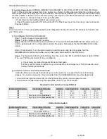
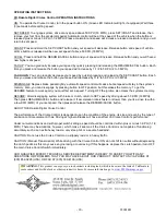
The CRUISE MODULE must be programmed for the vehicle on which it is installed. The twelve (12) programming switches must be
set according to the chart below in order for the Cruise Control to operate properly. Figure 1
NOTE 1: Both the VSS (Gray) and TACH (Dark Blue) wires must be connected. (The lone Gray wire will not be used if the Magnetic
Sensor kit is used as it plugs direct to the “Optional Speed Sensor” plug).
NOTE 2:
If using an “Open Circuit” control switch with the Cruise Control, Switch number twelve (12) will have to be OFF. If you are
unsure as to whether the control swi
tch is “Open Circuit” or “Closed Circuit”, look at the label of the packaging in which the switch
came.
NOTE 3: If any of the twelve (12) switches need to be changed after installation of the Cruise Control, the control switch and the
vehicle ignition must be in the OFF position; this is to allow the Cruise Control to RESET.
The twelve (12) programming switches are located under the Black Rubber Grommet on back of the CRUISE MODULE.
Figure 1 represents the twelve (12) programming switches for a vehicle characterized by:
-Switch (1 & 2) Gain Sensitivity Fig.1 -
ON=UP
-Switch (3 thru 6) VSS Pulses Per Mile
-Switch (7 thru 9) Engine Cylinder Setup Timer
-Switch (10) Square/Sine Wave Input
-Switch (11) Manual/Automatic Transmission
-Switch (12) Closed/Open Circuit Control Switch
Programming Functions:
*
VEHICLE’S COMPUTER (or 3 wire pulse generator)
** AUXILIARY VSS SOURCE (signal generator or magnet kit)


