370 S 370 S L 370 PP 370 PP L
6
UNPACKING AND INSTALLATION
Unpacking
A: Remove box or shrink wrap. Carefully inspect the machine for any physical damage. If damage is noted, notify the
truck line at once. They may require an inspection and a claim to be filed.
B: Remove the metal banding that holds the machine to the skid.
WARNING!!!!!
The banding can be sharp and cause injury.
C: Check that all standard parts and optional accessories are with the machine. Some accessories may be located in
chip drawer or behind access doors. Each machine should include one blade, one gallon of coolant, tool kit, owner’s manual,
and saw pitch calculator.
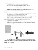
D: Remove the machine from the skid. If using an over head hoist, place a sling (part “A” shown below) around the
gear box Put the sling (part “B” shown below) around the feeder portion of the machine.
DO NOT PLACE SLING AROUND
THE FEED CYLINDER!
The sling is to stabilize the machine while lifting, and is not intended for lifting a large load.
When lifting the 370 Semi-Automatic saw, use only one sling around the gear box.
Always take proper precautions
when lifting these machines. If the machine slips or moves while lifting injury may occur. If a fork lift is used to move
the machine, make sure the weight is distributed evenly and the forks are all the way through before lifting.
E: Set the machine in the location where it will be operated.
Make sure saw is located in such a way that it will not
interfere with surrounding equipment. The machine must not be in a location where unsafe working conditions may
exist.
F: Discard packing materials in a safe manner. Make sure all the accessories and literature have been removed.
Installation
A: Clean off all surfaces that have been greased or coated with rust inhibitor.
B: After machine is in place on a level flat surface, adjust leveling bolts located in the foot flange of the machine base.
Adjust the machine so that it does not rock from floor irregularities.
C: From the main power, source connects power to the machine.
This power source must supply the machine with a
separate breaker of proper amperage.
For a 220 volt machine a 20 amp service is recommended. For a 440 volt machine a
Summary of Contents for Euromatic 370 S
Page 9: ...370 S 370 S L 370 PP 370 PP L 9...
Page 10: ...370 S 370 S L 370 PP 370 PP L 10 Actual control panel layout may vari...
Page 32: ...370 S 370 S L 370 PP 370 PP L 32...
Page 33: ...370 S 370 S L 370 PP 370 PP L 33...
Page 38: ...ALIMENTAZIONE 230V 60Hz 230V 60Hz POWER SUPPLY POWER SUPPLY...
Page 39: ...HL4 ILLUMINAZIONE LAMA POWER SUPPLY...
Page 40: ...LAMPEGGIATORE LAMA IN MOTO 24VAC MORSA 24VAC EMERGENCIES...
Page 44: ...9 11 2 4 5 10 3 6 7 8 1 CH1 LC4HR424ACJ KA5 RITORNO CARRO COUNTER...
Page 45: ...TERMINAL...
Page 49: ...10 2 2019 Euromatic 370 2 Head Cylinder Unit Ref 005...
Page 51: ...10 2 2019 Euromatic 370 4 Bedplate Unit Ref 008...
Page 53: ...10 2 2019 Euromatic 370 6 Head Unit Ref 002...
Page 55: ...10 2 2019 Euromatic 370 8 Vise Unit Ref 004...
Page 57: ...10 2 2019 Euromatic 370 10 Group Feeder P R...
Page 59: ...10 2 2019 Euromatic 370 12 Group Alimentador P P Ref 014b Alimentador Ref 014b...


