370 S 370 S L 370 PP 370 PP L
17
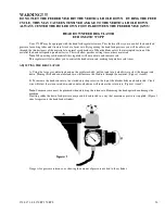
The air pressure can also be reduced by turning the main incoming air regulator down. Turning this down will also
slow the operation of the machine.
WARNING!!!!!
BE SURE CAM IS TIGHT; DAMAGE TO THE MACHINE AND/OR PERSONAL INJURY MAY
OCCUR
Warning!!!!!
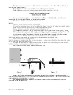
Never depress the limit switches with your finger. Your finger could be crushed or amputated
between the limit switch and cam block.
SEMI-AUTOMATIC CUTTING
370 PP / S
Running in the Semi-Auto mode
WARNING!!!!
Always close the safety guard when the machine is in operation.
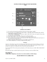
A: Turn on the main power to the saw.
B: With the 370 PP model turn the cycle selector switch to the semi-auto selection (hand symbol)
C: Turn the security key to the on position (LEFT)
D: Set up and adjust your vises to the material being cut. (See vise set up section)
E: Set up your head parameters. (See head limit section)
F: Place part against positive stop, or position material for correct length to be cut.
WARNING!!!!!
NEVER MOVE THE BLADE SPEED SELECTION KNOB WHILE THE MACHINE IS IN
OPERATION OR WHILE THE GREEN OR YELLOW LIGHT IS ON, IT MAY DAMAGE THE
MACHINE.
G: Select speed. 25 or 50 RPM for ferrous material, 15000 or 3000 for non-ferrous material
H: Close head feed flow control.
I: Press the green start button. (370PP you will need to press the orange button after pushing the green button) Adjust
the head feed rate, and coolant flow to the material being cut.
WARNING!!!!!
Make sure head feed control is closed before starting cycle. Head could overfeed into the part
if this is not followed, causing possible blade and/or machine damage, or may result in personal injury.
The following steps will be executed
1. Vises close and clamp the part.
2. Motor starts, coolant flow starts. Head will descend and make cut.
3. Motor stops, coolant flow stops. Head will return to the preset height.
4. Vise will unclamp part.
VISE SET-UP AND MITER CUTTING
FERROUS HEAD
Miter cutting and Squaring
The 370 PP and 370 S have a scale scribed into the front of the rotating portion of the cutting head (0 to 60 degrees.)
On the stationary portion of the cutting head casting is a scribed line. Any angle can be set by loosening the lock handle. This
handle is located front and center of the cutting head.
Loosen the locking handle, this handle can be pulled and repositioned to clear the coolant tube.
Summary of Contents for Euromatic 370 S
Page 9: ...370 S 370 S L 370 PP 370 PP L 9...
Page 10: ...370 S 370 S L 370 PP 370 PP L 10 Actual control panel layout may vari...
Page 32: ...370 S 370 S L 370 PP 370 PP L 32...
Page 33: ...370 S 370 S L 370 PP 370 PP L 33...
Page 38: ...ALIMENTAZIONE 230V 60Hz 230V 60Hz POWER SUPPLY POWER SUPPLY...
Page 39: ...HL4 ILLUMINAZIONE LAMA POWER SUPPLY...
Page 40: ...LAMPEGGIATORE LAMA IN MOTO 24VAC MORSA 24VAC EMERGENCIES...
Page 44: ...9 11 2 4 5 10 3 6 7 8 1 CH1 LC4HR424ACJ KA5 RITORNO CARRO COUNTER...
Page 45: ...TERMINAL...
Page 49: ...10 2 2019 Euromatic 370 2 Head Cylinder Unit Ref 005...
Page 51: ...10 2 2019 Euromatic 370 4 Bedplate Unit Ref 008...
Page 53: ...10 2 2019 Euromatic 370 6 Head Unit Ref 002...
Page 55: ...10 2 2019 Euromatic 370 8 Vise Unit Ref 004...
Page 57: ...10 2 2019 Euromatic 370 10 Group Feeder P R...
Page 59: ...10 2 2019 Euromatic 370 12 Group Alimentador P P Ref 014b Alimentador Ref 014b...


