background image

Super Wiring System

Si30-408

16

Introduction

4.2

Wiring Length

„

In super wiring system, limit the wire length within the following number except the wiring of 
remote controller, due to standardization of wiring for connection between outdoor and 
indoor unit and centralized transmission lines.

The farthest length: 1000m or less, 
the total wiring length: 2000m or less

(When using sheathed wire, the total wiring length can be 1500m or less)

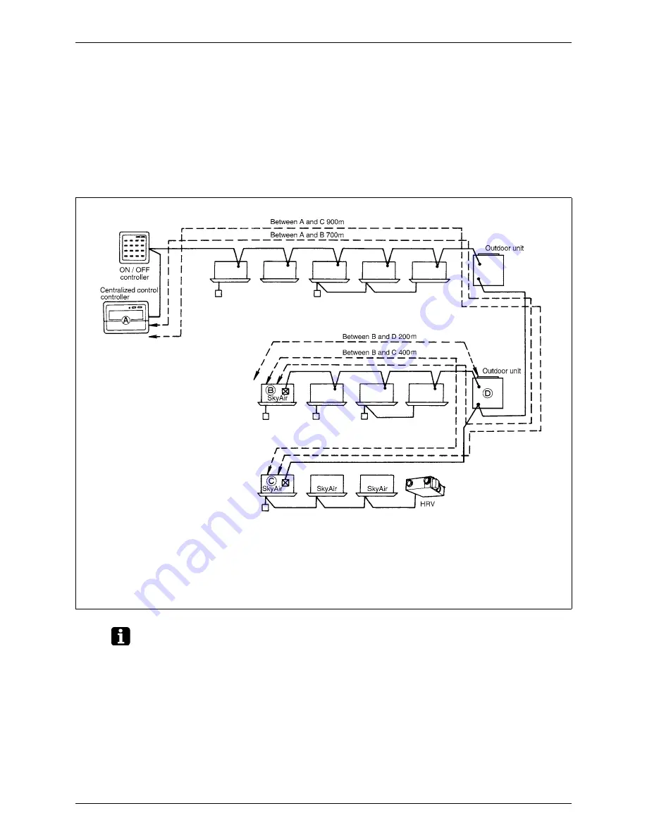
Example of System

Note:

Be sure to check the farthest length and the total wiring length in designing.
If the sum of lengths exceeds the restricted limits, divide the system, or install more DIII-NET 
expander adapters as countermeasures.

„

In the above system, the farthest connecting distance is 900m between (A) and (C), conforming the condition of the 
farthest length of 1000m or less, and the total wiring length is 1100m, the sum of 900m between (A) and (C) plus 
200m between (B) and (D), also conforming the condition of 2000m or less.
Thus, as long as both the farthest length and the total wiring length stay within the limits, the system operates 
without any trouble.

Summary of Contents for VRV

Page 1: ...Si30 408 Basic Training Manual...

Page 2: ...on trouble shooting and trouble removing corresponding to the computerized and systematized products are required Based on these requests therefore we have prepared this manual emphasizing the underst...

Page 3: ...General Contents General Contents A Introduction 1 B Basic Information 21 C Field Settings from Remote Controller 41 D Troubleshooting 67 E Cases for Examination 109 F Service Checker Type3 Applicatio...

Page 4: ...Si30 408 ii General Contents...

Page 5: ...Unit Models 3 2 2 Nomenclature 5 3 System Basic Configuration 11 3 1 Cooling Heating Selection Standard System 11 3 2 Heat Recovery Cooling Heating Individual Operating System 14 4 Super Wiring System...

Page 6: ...oor unit The expansion valve is mounted to the outdoor unit only SKY AIR System for Simultaneous Operation Twin Triple and Double Twin These series are included in SkyAir These types can be connected...

Page 7: ...ter KU series Model Type Service manual Model Type Service manual RSXY5 10H J RSX5 10H J Heat pump Cooling only Si 46C Si 46C RSX5 10KU Cooling only Si 91 VRV Inverter KA series Model Type Service man...

Page 8: ...y Si 96 High COP Inverter Type VRV High COP type L series Model Type Service manual RSXYP5 10L Heat pump Si33 201 Large Capacity Inverter Type VRV Plus series Model Main unit Sub unit Type Service man...

Page 9: ...HP 125 5 HP 25 1 HP 63 2 5 HP 200 8 HP 32 1 25 HP 80 3 2 HP 250 10 HP 40 1 6 HP 100 4 HP Refrigerant type No indication R22 P R407C Type of unit C Ceiling mounted cassette type Double flow F Ceiling...

Page 10: ...z Indicates major design category B New ceiling suspended cassette K Wall mounted type 40 63 Capacity Indication Conversion to horsepower 40 1 6HP 50 2 0HP 63 2 5HP 71 3 HP 100 4 HP 125 5 HP Refrigera...

Page 11: ...to horsepower 71 3HP 140 6HP Type of Unit Connection Unit BEV K VE 71 V2864 V1 Single phase 220 to 240V 50Hz Indicates major design category Capacity Indication Connectable total indoor unit capacity...

Page 12: ...8 8 HP 18 18 HP 26 26 HP 10 10 HP 20 20 HP 28 28 HP Refrigerant R407C No indication R22 Indicates that this is a RSXY Heat Pump RSEY Heat Recovery RSX Cooling Only 16 E P RSX V2288 The unit with anti...

Page 13: ...ng mounted cassette type Multi flow K Ceiling mounted cassette corner type S Ceiling mounted built in type M Ceiling mounted duct type H Ceiling suspended type A Wall mounted type L Floor standing typ...

Page 14: ...2 HP 30 30 HP 40 40 HP 8 8 HP 16 16 HP 24 24 HP 32 32 HP 42 42 HP 10 10 HP 18 18 HP 26 26 HP 34 34 HP 44 44 HP 12 12 HP 20 20 HP 28 28 HP 36 36 HP 46 46 HP 38 38 HP 48 48 HP Refrigerant R410A No indic...

Page 15: ...control Normal motorized valve SH control Master Slave Slave Controls operation mode by using four way valve Changing of outdoor heat exchanger to condenser or evaporator Selection for cooling heatin...

Page 16: ...il equalizer To indoor units Two pieces of piping for liquid and gas Cooling Mode Cooling Mode Normal motorized valve SH control Normal motorized valve SH control Master Slave Slave R22 R22 Selection...

Page 17: ...ng Mode Normal motorized valve SH control Normal motorized valve SH control Master Slave Slave Controls operation mode by using four way valve Changing of outdoor heat exchanger to condenser or evapor...

Page 18: ...e SC control Master Slave Master Controls cooling and heating by selection the inside solenoid valve Control operation mode by using plural four way valves Outdoor heat exchanger is divided and change...

Page 19: ...F2 I O N P F1 I O N N P Indoor unit Power supply Single phase 200 V Remote controller Power supply 3 phase 220 V or 380 415 V A B C Cooling heating selection remote controller O O I O Outdoor unit A M...

Page 20: ...of System Note Be sure to check the farthest length and the total wiring length in designing If the sum of lengths exceeds the restricted limits divide the system or install more DIII NET expander ada...

Page 21: ...or unit master to Outdoor unit slave a 1 branch kit to Indoor unit c Outdoor unit to Indoor unit b c Allowable length m 5m or less 40m or less 120m or less Between outdoor unit and indoor unit H1 Betw...

Page 22: ...unit 1 Outdoor unit 2 Indoor units Indoor units Indoor units 1 refrigerant branch kit Outdoor branch kit b REFNET header Outdoor branch to Outdoor unit a 1 branch kit to idoor unit c Outdoor branch t...

Page 23: ...t on Equivalent Length of Joint For Reference Unit m Piping size Tightening angle guideline Recommended arm length of tool 6 4 60 90 Approximately 150mm 9 5 60 90 Approximately 200mm 12 7 30 60 Approx...

Page 24: ...REFNET Piping Si30 408 20 Introduction...

Page 25: ...1 Cooling Operation 24 3 2 Heating Operation 25 3 3 Compressor Capacity Control 26 3 4 Control of Electronic Expansion Valve 27 4 Control of Indoor Unit 28 4 1 Thermostat control 28 4 2 Drain Pump Co...

Page 26: ...tersection above can be obtained by measuring pressure and temperature of refrigerant at a certain point As to single refrigerants R22 R134A etc isothermal line has no gradient in the saturated area t...

Page 27: ...ree The difference between temperature and pressure equivalent saturation temperature in subcooled liquid is called subcooled degree SC In order to prevent wet operation the superheated degree is made...

Page 28: ...ion temperature Te close to target value Superheated Degree Control of Indoor Electronic Expansion Valve In order to maintain the superheated degree in evaporator and to distribute proper refrigerant...

Page 29: ...n valve is so controlled as to put superheated degree at evaporator outlet close to target value Superheated degree SH outdoor suction pipe temperature outdoor evaporating temperature Subcooled Degree...

Page 30: ...d an inverse installation outdoor unit is placed lower than indoor unit may increase liquid pipe inside resistance In such case lower setting of target evaporation temperature by using field setting w...

Page 31: ...fference between setting temperature and suction air thermistor temperature T When SH SHS adjust to make opening degree wider than the present one When SH SHS adjust to make opening degree narrower th...

Page 32: ...ge of remote controller thermostat In such a case install the remote controller thermostat in the room where there is no influence of outdoor air Preset temperature TS Suction temperature TH1 12 14 16...

Page 33: ...eld setting Refer to page 43 and page 44 for changing 4 1 3 Thermostat control in Dry Operation In dry operation control is made based on suction temperature at the time of operation start Fan is driv...

Page 34: ...mostat Operation Float switch Drain pump 5 min 1 Residual operation 5 min 5 sec ON OFF ON OFF ON OFF Malfunction stop with A3 on remote controller Thermostat Operation Float switch Drain pump 5 min 5...

Page 35: ...uneasy Aiming to limit the frequency of thermostat on off and keep comfortableness Wide range of continuous operation can be kept Aiming to maintain reliability of compressor The frequency of compres...

Page 36: ...e transmitted from outdoor 50 C Th2 Indoor liquid pipe thermistor 43 C Off Condition Any One of the Conditions below should be Satisfied Becomes any mode except heating Thermostat off Under hot starti...

Page 37: ...ifferential valve is 5 C As to charging method of setting value refer to page 43 and page 44 Cooling Heating Differential at 5 C Automatic heating 22 C Automatic cooling 27 C Display selection Cooling...

Page 38: ...stat turns off if the temperature does not reach setting temperature 3 C cooling operation should not be on Automatic heating 22 C Automatic cooling 25 C Display selection Cooling Heating Display sele...

Page 39: ...tat off with limitation on retrying Oil return control Based on cumulative operation time oil return operation should be carried out periodically According to the state of operation cumulative operati...

Page 40: ...For RSXY8 10K and RSXYP8 10KJ Schematic Diagram of Refrigerant Rev C F R Th2 SENPH U SENPL V T Th4 Th3 2 S Th3 1 S Th3 Y Th1 W Th3 Y Th1 W Th2 X L Th2 X L Th3 Y Th1 W Th2 X L K K K J G D H H A B STD C...

Page 41: ...ubcooled degree SH Tg Tl control in cooling operation Components of outdoor unit A Inverter compressor INV MC1 Used to conduct the capacity control constant Te control in cooling constant Tc control i...

Page 42: ...be Four way valve Electronic expansion valve Electronic expansion valve Pressure sensor High pressure Compressor Compressor Compressor Solenoid valve Pressure sensor Low pressure Filter To oil equaliz...

Page 43: ...trol and the compensation of electronic expansion valve control Liquid pipe thermistor Tl R2T Used to control superheated degree SH Tg TI in cooling operation Used to freeze up prevention control Used...

Page 44: ...avoid increase in pressure at abnormal hating due to fire the fusible part melts at a temperature of 70 to 75 C thus relieving pressure into atmosphere T Pressure regulating valve 1 Receiver to Disch...

Page 45: ...d Settings from Remote Controller Remote Controller Remote Controller Remote Controller 1 Field Settings from Remote Controller 42 1 1 Field Setting Mode 43 1 2 Service Mode 49 1 3 Check Mode 54 1 4 T...

Page 46: ...u t t o n o n c e o r a f t e r 3 0 m i n u t e s After 10 seconds Following codes can be checked as often as pressing CHECK TEST button once C 1 Special Field Setting Mode No 50 B 1 Display of Servic...

Page 47: ...e system into field setting mode While in normal mode press and hold the button for a period of four seconds or more to put the system into Field Setting Mode Select mode No Select a desired mode No u...

Page 48: ...n output Abnormal output 1 External ON OFF input Make this setting to conduct ON OFF operation from outside Forcedly OFF ON OFF operation When external protection device is connected 2 Thermostat sele...

Page 49: ...r operation is occasionally not accepted displaying 88 for a period of about one minute Put the system into setting mode While in normal mode press and hold the button for a period of four seconds or...

Page 50: ...the button for a period of four seconds or more to put the system into Field Setting Mode Select mode No Select mode No 30 using button Select unit No Select unit No using button Select group No Selec...

Page 51: ...ngs from Remote Controller 47 Examples of Address Settings Group No for centralized control 1 00 1 2 3 1 01 For remote control and connecting each indoor units to DIII net 1 03 00 1 00 SETTING AIR CON...

Page 52: ...ly Check installation and electric wiring again before turning on the power supply In turning on the power supply after all LCDs are displayed the operation is occasionally not accepted displaying 88...

Page 53: ...on Select unit No For group control only Select indoor unit No to be set using button Select malfunction history No or sensor data No Select a desired malfunction history No or sensor data No by using...

Page 54: ...data Displays various types of data Select the data to be displayed with the button Sensor data 0 Remote controller thermostat 1 Suction 2 Liquid pipe 3 Gas pipe Address data 4 Indoor unit address 5 O...

Page 55: ...g While in wireless remote controller select the upper and lower button Make required settings in each mode In mode 44 and 45 press the button before setting so that the setting change can be made The...

Page 56: ...f each indoor unit will be forcedly turned on forcedly ON individually 44 Individual setting Select the unit by using button Set the air flow rate with the button Set the air flow direction with the b...

Page 57: ...ply Check the installation and electric wirings once again before turning on the power supply When the power supply is turned on there may be cases where any operation cannot be accepted with 88 displ...

Page 58: ...on once 1 Malfunction code is displayed 2 Press the button once again 1 Indoor model code is displayed 3 Press the button one more time 1 Outdoor model code is displayed Refer to a list on malfunction...

Page 59: ...by operating the button of remote controller 1 4 1 Setting of Test Operation Mode Test operation mode setting is available by operating as follows After setting of test operation mode pressing the bu...

Page 60: ...hanges of operating conditions or settings of a variety of addresses mainly for service work 3 Monitor mode H1P Blinking This mode is used to check the contents set in Setting mode 2 Procedure for Cha...

Page 61: ...g items No 2 3 and 4 can select the cooling heating selection method After setting press the RETURN button BS3 to determine the content Pressing the RETURN button BS3 puts the system into the initial...

Page 62: ...el when the low noise signal is input from outside 26 Starting time of nighttime low noise operation Sets the starting time of the nighttime low noise Setting of the nighttime low noise is required 27...

Page 63: ...7 8 7 7 7 High Normal Low 8777877 8777787 8777778 9 Correction of the pressure loss in piping Select according to the piping length and scale of the pressure loss 8 7 7 8 7 7 8 High Normal Low 877787...

Page 64: ...8 7 7 OFF ON 8777778 8777787 29 8 7 8 8 8 7 8 OFF ON 8777778 8777787 30 8 7 8 8 8 8 7 60 demand 70 demand 80 demand 8777778 8777787 8777877 32 8 8 7 7 7 7 7 OFF ON 8777778 8777787 38 For emergency me...

Page 65: ...8 8 7 7 Lower four digits upper 13 The number of terminals 9 7 7 8 8 7 8 Lower four digits lower 14 Content of malfunction latest 3 8 7 7 8 8 8 7 Refer to page 104 Malfunc tion code list in the chapt...

Page 66: ...2 in decimal number As a result the address becomes 22 For example the number of terminal units for Nos 12 and 13 is expressed in eight digit binary number which are the combination of four upper and...

Page 67: ...utdoor unit system and to close liquid side stop valve completely With opening status the refrigerant cannot be charged 3 Set A additional refrigerant charge operation ON in stop state by using the H1...

Page 68: ...he liquid side stop valve 3 Setting of service mode 4 It is completed if the refrigerant is charged to the specified capacity If the charge is not completed within 30 minutes make the setting again an...

Page 69: ...ode can be released by resetting the power supply of outdoor unit 2 2 3 Setting of Evacuation Mode When the refrigerant is recovered in the field open the expansion valves in indoor and outdoor units...

Page 70: ...minimum opening degree at start of the motorized valve Stopping Pressure equalizing Cooling start control Cooling stability waiting Various judgment functions Pump down residual operation Standby for...

Page 71: ...n of Electronic Expansion Valve 83 3 4 Structure and Movements of Four way Valve 85 3 5 Structure and Operation of Solenoid Valve 87 3 6 Structure and Operation of Two way Solenoid Valve 88 3 7 Check...

Page 72: ...he operating conditions and then record them in the operating condition check sheet p 108 3 Referring to the book of case examples check to be sure whether applicable information is described 4 Using...

Page 73: ...ontroller Liquid pipe temperature No 41 on remote controller Gas pipe temperature No 41 on remote controller Opening degree of electronic expansion valve Other Check Items Number of indoor unit connec...

Page 74: ...ure to grasp the state by using the checker Year round cooling Outdoor unit short circuit Low outdoor temperature control High pressure stepping down protection control Excessively light load short ci...

Page 75: ...rban area Excessively frequent defrosting operation Operation standby due to outdoor temperature Refrigerant depositing in the indoor unit not in operation Rising of high pressure due to excess refrig...

Page 76: ...t cannot be super heated at the outlet of heat exchanger and liquid refrigerant which does not evaporate returns to compressor resulting an operation so called wet operation Superheated degree 0 The d...

Page 77: ...rises due to decreasing of compressor output Progress of excessive gas charging No status change within the range that the receiver can absorb the refrigerant Frequency becomes to the minimum Outdoor...

Page 78: ...Frequency Heating Fan control will be executed for maintaining high pressure with low outdoor temperature cooling control Actually hunting will be generated Low pressure is maintained constant High p...

Page 79: ...C R31T 165 0 C 20 0 C J3 Discharge pipe thermistor For STD Th3 2 196 0 C 10 2 C R3 2T 165 0 C 20 0 C R32T 165 0 C 20 0 C J3 Suction pipe thermistor Th4 90 0 C 10 2 C R6T 90 0 C 43 6 C R2T 90 0 C 43 6...

Page 80: ...door electronic EV closes When the resistance deviates to larger value Lower temperature detected Superheated degree SH Tg Tl Tg Tl increases Indoor electronic EV opens Superheat operation cooling cap...

Page 81: ...door electronic extension valve opens Liquid refrigerant is stagnant in indoor heat exchanger High pressure rises due to heating overload Refrigerant delivery among indoor units cannot be balanced Ind...

Page 82: ...or For Thermistor Malfunction No Name Material 1 Thermistor Metallic oxide Glass Dumet wire 2 Coat agent 1 Silicon resin 3 Coat agent 2 Epoxy resin 4 Filling agent Epoxy resin 5 Protective pipe Phosph...

Page 83: ...1 208 9 191 5 175 8 12 67 11 70 10 82 10 01 9 27 30 32 34 36 38 16 1 14 8 13 6 12 5 11 5 15 6 14 2 13 1 12 0 11 1 161 5 148 4 136 6 125 8 116 0 8 60 7 98 7 41 6 89 6 42 40 42 44 46 48 10 6 9 8 9 1 8 4...

Page 84: ...olor of harness is not as mentioned above find the measuring point by following procedure 1 Black is GND 2 Find DC5V line 3 The remained wire is the sensing section For the same pressure higher output...

Page 85: ...e PL VL 0 5 0 98 3 PH Detection pressure High pressure side MPa PL Detection pressure Low pressure side MPa VH Output voltage High pressure side VDC VL Output voltage Low pressure side VDC Output volt...

Page 86: ...Detection pressure High pressure side MPa PL Detection pressure Low pressure side MPa VH Output voltage High pressure side VDC VL Output voltage Low pressure side VDC Output voltage VH VL 0 5 1 0 5 0...

Page 87: ...or subcooled degree control In the valve single phase excitation drive type pulse motor is employed On receiving 2000 pls signal goes to full open The stroke of gear is 0 7 mm from full open to compl...

Page 88: ...iving section Crack is found in bellows Gears run idle due to wear of gear teeth The valve is protruded excessively into the valve seat When driving section of electronic expansion valve is removed du...

Page 89: ...r While in cooling and defrosting in heating the valve feeds to outdoor heat exchanger For VRV system standard unit one four way valve is installed however for some units of other series plural valves...

Page 90: ...tion in Heating From discharge of compressor Internal piston moves according to pressure difference between high pressure and low pressure To indoor heat exchanger To suction of compressor From outdoo...

Page 91: ...suction port from liquid line reducing pressure through capillary tube The operation is as follows Plunger which is a slide part inside valve body lifts to make a flow of refrigerant when the coil is...

Page 92: ...In operation of standard outdoor unit In no operation of standard outdoor unit Cooling operation Valve state open not energized The line including the valve functions as a low pressure line of each st...

Page 93: ...ck on the following items Pulses approx 0 V and approx 5 V can be output for four times between pin No 1 and 5 in X2A Pulses approx 0 V and approx 5 V can be output for four times between pin No 2 and...

Page 94: ...30 Hz or less Overload Electronic thermal detector 54 A detected in some cases Main causes In normal operation Control PC board Inverter PC board Power unit Detect signal of power unit with inverter...

Page 95: ...r PC board and INV PC board INV PC board Outdoor PC board LO Faulty inverter PC board The safety device of inverter system activates in microcomputer on inverter Only for G INV PC board Power transist...

Page 96: ...on cannot be determined When the retry frequency completes within 60 minutes malfunction is determined and malfunction code will be displayed on indoor remote controller 9 BLINK 8 ON 7 OFF LED A 1 2 3...

Page 97: ...cking will be required make sure to execute continuity check yourself to grasp the equipment system correctly Grasping the actual system can suggest measures for improving incorrect branch wiring or f...

Page 98: ...ich points the waveforms have been acquired It is useful for measurements to provide a temporary distributing cable 3 9 3 Measurement Range Basically time axis lateral axis 50 s to 100 s voltage axis...

Page 99: ...e Too long wiring length too many units connected or branches of wiring Installation of D III NET expander adapter Separating the system Resistance in the end of line cannot be used Ringing High volta...

Page 100: ...le explanation can be accepted With this method the causes can be analyzed logically and reasonably and causes can also be narrowed down by using a process of elimination Moreover in explanation or re...

Page 101: ...of pressure Faulty actuation of expansion valve Piping resistance high Run out of gas Dirty evaporator Load too small Air flow drop Faulty control PC board Faulty low pressure sensor Faulty expansion...

Page 102: ...ssure Outside of scope of using outdoor air temp Fault outdoor thermistor Piping resistance high Faulty model selection Outside of application scope Operation capacity low Non condensible gas mixed Di...

Page 103: ...rature Discharge temperature rises False detection of discharge pipe temperature Faulty discharge pipe control Faulty compressor Refrigerant circulation volume shortage Faulty discharge pipe thermisto...

Page 104: ...or between partition plates of heat exchanger come out from contacting part with tube sheet and come into contact with heat exchanger resulting water leakage Water leakage Waterdrop fall down from fin...

Page 105: ...mpressor stop start Wet operation Abnormal overheat operation Moisture mixed Foreign matter contamination Clogged oil return capillary Clogged oil separator Refrigerant charging low Faulty expansion v...

Page 106: ...ssor Malfunction of thermistor for discharge pipe Faulty thermistor for low pressure equivalent saturation temperature Malfunction of thermistor for suction pipe Malfunction of thermistor for air heat...

Page 107: ...xchanger Secondary side Malfunction of thermistor for sub tank Malfunciton of oil temperature thermistor system Malfunction of thermistorforheating heat exchange Primary side Compressor overload Motor...

Page 108: ...heat exchange temperature Malfunction of Tb sensor J6 Malfunction of sensor for receiver temperature Malfunction of Tl sensor J7 Malfunction of sensor for oil pressure equalizing pipe temperature Malf...

Page 109: ...7 5 5 7 E7 5 7 5 5 5 5 7 5 E9 5 5 7 7 5 5 7 5 5 5 7 5 5 5 H7 5 7 5 7 7 5 7 5 5 5 5 7 5 H9 5 5 7 7 5 5 7 7 HC 5 5 5 7 7 5 7 7 HJ 5 5 5 7 5 5 7 7 HF 5 5 5 5 5 5 7 7 F3 5 7 5 7 5 5 7 7 5 5 5 7 7 F6 5 7...

Page 110: ...verter open phase phase T Malfunction of charging for capacitor in inverter main circuit Check operation not executed U3 Faulty transmission between indoor units and outdoor units Malfunction of I O t...

Page 111: ...7 5 7 7 7 5 5 7 7 P3 5 7 7 5 5 5 7 7 P4 5 7 5 7 7 5 7 7 PJ 5 5 5 7 5 5 7 7 U0 5 5 7 7 5 5 7 7 7 7 5 7 7 U1 5 7 7 7 5 5 7 7 U2 5 7 7 5 7 5 7 7 U3 5 7 7 5 5 5 7 7 U4 5 7 5 7 7 5 7 7 U7 5 7 5 5 5 5 7 7...

Page 112: ...rop R S V S T V T R V Compressor operation capacity Measure with clamp meter INV Hz STD1 ON OFF STD2 ON OFF High pressure Measure with pressure gauge service checker After 20 minutes or later from ope...

Page 113: ...for Examination 109 E Cases for Examination E Cases for Examination E Cases for Examination E Cases for Examination 1 VRV in General 110 2 Indoor Unit Related Examples 121 3 Malfunction of Transmissio...

Page 114: ...f Diagnosis When examining multiple outdoor units do not inspect only the inverter outdoor units but inspect STD outdoor units 1 and 2 1 2 Malfunction F6 is Displayed during Check Operation in the Win...

Page 115: ...t must be connected not only with pipes but with wires 1 4 After Replacement of the Control PC Board Operation does not Start with an Malfunction LC Displayed Applicable Models RXYP KJ and RXEP KJ VRV...

Page 116: ...the slave unit of outdoor multi connection was blinking Cause Instead of connection of outdoor multi terminals Q1 and Q2 outdoor to outdoor F1 and F2 connection was being applied at the time of multip...

Page 117: ...even if an erroneous connection exists Be sure to execute a test operation check operation on an individual unit Check whether there is an erroneous connection if an malfunction E4 or an malfunction F...

Page 118: ...setting of remote controller s thermostat to enabled Point of Diagnosis 1 9 Malfunction Heating Operation Applicable Models VRV in general Type K or later models Condition If all thermostats are turn...

Page 119: ...ower to the crank case heater for 6 hours 1 11 No Heating Operation is Available though Cooling Operation is Possible Fan only Operation Continues with no Malfunction Displayed Applicable Models VRV i...

Page 120: ...g indoor units work well and reach the set temperature The pressure of the outdoor units for low pressure use evaporating temperature has reached the target value Liquid pipe temperature of the faulty...

Page 121: ...he electronic expansion valve of outdoor units leading to the wet operation The low pressure at that time comes to be 0 2MPa due to minimum EV opening Measure Recovers by correcting the refrigerant to...

Page 122: ...a service checker type III and check whether the superheated degree control of the indoor unit is normal 2 If the above checker is not available use a remote controller to check When replacing the com...

Page 123: ...uses an electronic expansion valve mounted to the indoor unit to control the flow rate capacity control of refrigerant In heating operation if the temperature of suction air of indoor unit closes to t...

Page 124: ...h the pump stopped Measure Recovers by correcting the wiring of the cooling heating select remote controller If a heating operation is displayed in the cooling only model confirm the terminal connecti...

Page 125: ...ure is displayed on the centralized controller Temperature is displayed on the remote controller Cause Since the outside air processing air conditioner is controlled based on the discharge air set tem...

Page 126: ...ne from the humidifier are designed to flow together to the drain up kit and the drain up kit is designed to operate when voltage is applied However the drain flows back and is not drained completely...

Page 127: ...n line had been laid next to the high voltage line of the elevator Measure Request to correct wiring Point of Diagnosis 3 2 Malfunction of Transmission Examples Malfunction of Transmission due to Wiri...

Page 128: ...ne However multi core lines are used actually There was also a case where two cores out of four cores were being used for power supply Measure Request to correct the wiring Point of Diagnosis 3 4 Malf...

Page 129: ...easure The short circuit line was removed Before taking measures check the condition because the forced stop input may have been wired intentionally based on the facility conditions on site Point of D...

Page 130: ...e Completed by mounting a DIII NET expander adapter Point of Diagnosis 3 8 Malfunction of Transmission Examples Faulty Condition Caused by Branch Lines Applicable Models VRV in general Condition A tra...

Page 131: ...ayback of Data Recorded 144 4 Collection and Playback of Data on Checker 146 4 1 Retrieval of Raw Data 147 4 2 Retrieval of Processed Data 149 4 3 Data Processing 151 4 4 Organizing Graph 168 4 5 Usin...

Page 132: ...mer Connection D3 D3 NET connection Soft Ver Support software version A blank is Ver 1 03 or before it PCB PCB connection VRV series HFC Connection Soft Ver Type Model D3 PCB R410A VER II M series Hea...

Page 133: ...ame is displayed in HiVAV System Since this is a correct display however use these indoor units as it is 8 Connect any model of VRV Plus series to applicable function units or cooling plus units 9 If...

Page 134: ...Service Checker makes it possible to check the conditions of and operate indoor units in the following cases The Service Checker Type3 enables the operation equal to that accomplished with centralized...

Page 135: ...e operating conditions and look at why this control is performed Each stepping down and protection control is used to ensure reliability not to protect malfunctions For example do not determine that t...

Page 136: ...Edition Procedure Select and click an applicable item on the main menu Procedure Click on the Customer Name Site Name registration tab If the Customer Name registration has been made click on the Sele...

Page 137: ...ker Can Do Service Checker Type3 Application Edition 133 Procedure Register the Customer ID and Customer Name Site Name For the registration only enter the Customer ID and Customer Name For any other...

Page 138: ...What Service Checker Can Do Si30 408 134 Service Checker Type3 Application Edition Procedure Register the system Select menu For a new customer or For a project with Customer Name registered...

Page 139: ...s case clicking on the Yes will stop all systems connected to the DIII NET for a period of several minutes which has ever resulted in a claim regarding the server room of hospital If the Checker is co...

Page 140: ...have been made and the window has been switched if no data is read and the above error is displayed on the window the following causes will be supposed F1 and F2 is not well connected PC board is not...

Page 141: ...ts are properly read the above window will appear If the above window appears select an operation to be conducted on the menu icons Caution The number of outdoor units varies with the number of sensor...

Page 142: ...layback of Operation Data Si30 408 138 Service Checker Type3 Application Edition Selecting recording mode F5 will display the above window Click on the Period rcd set button and make setting of period...

Page 143: ...ecording Setting Window Make settings of periodical recording Selection of system to be recorded Be conscious only to select a system for which data should be collected Otherwise data memory will run...

Page 144: ...dition Make settings of periodical recording Setting of recording intervals Set the recording intervals to 60 seconds unless otherwise specified by Quality Control Dept or else Be sure to check the fr...

Page 145: ...tings of periodical recording Click on the Period rcd Start button Periodical recording starts Check whether or not the recording process is in progress Check to be sure In period recording is display...

Page 146: ...on button on the Menu window The centralized operation is the same as operation on centralized remote controller Caution Address settings should be made on the remote controller for indoor units 3 4 D...

Page 147: ...on data can be displayed even while in recording mode Click on the Detail data input button on the Menu window The above window will be displayed Digital data will be displayed at the right on the win...

Page 148: ...ck of operation data Click on the Play button on the Menu window shown above Highlight data to be played back on the operation data shown in figure above and then click on the Ope data disp F1 button...

Page 149: ...the graph for a period of time shortened Reduction F2 Used to display the graph for a period of time prolonged Backward F3 Used to move the graph to the left on the window Forward F4 Used to move the...

Page 150: ...a personal computer Since time displayed on the Checker is corresponding to that displayed on the personal computer be sure to check and change the time If settings of screen saver and energy saving...

Page 151: ...data to e mail or else 1 Boot up the Checker software and then click on the Data transfer button 2 Use the following procedure to transfer the data 1 Check the Operation data in initial at this posit...

Page 152: ...le data file shown above to the e mail On the contrary in order to read data transmitted on the Checker download transfer the data to Checker by reversing the procedure 2 The following files of two ty...

Page 153: ...3 Application Edition 149 4 2 Retrieval of Processed Data 1 Boot up the Checker software and then click on the Play button 2 Use the following procedure to carry out CSV conversion of data 1 Highlight...

Page 154: ...ayback of Data on Checker Si30 408 150 Service Checker Type3 Application Edition 3 Use the following procedure to save converted data 1 Specify a place to save the data 2 Enter the data name 3 Click o...

Page 155: ...a collected after the CSV conversion This processing is a method of data analysis on the EXCEL window or in graphical form 1 Analysis of EXCEL Data Opening data CSV converted will display the window s...

Page 156: ...Collection and Playback of Data on Checker Si30 408 152 Service Checker Type3 Application Edition Adjust the width of columns...

Page 157: ...ker Type3 Application Edition 153 A number of ON and OFF are mixed on the current setting thus making the window hard to read Therefore make settings in accordance with the procedure shown below in or...

Page 158: ...30 408 154 Service Checker Type3 Application Edition Only ON s are displayed thus facilitating reading the data It is effective to replace a variety of functional parts and control e g four way valves...

Page 159: ...Si30 408 Collection and Playback of Data on Checker Service Checker Type3 Application Edition 155 Pane fixing...

Page 160: ...ion and Playback of Data on Checker Si30 408 156 Service Checker Type3 Application Edition The title on the first line and time in Column A of data series is fixed thus facilitating the Verification o...

Page 161: ...Si30 408 Collection and Playback of Data on Checker Service Checker Type3 Application Edition 157 Screening or coloring data to be noted facilitates the analysis on the data...

Page 162: ...extended period of one or two weeks to verify the case of intermittent occurrences of malfunctions the volume of data will become huge thus taking time to verify the data Using auto filter enables the...

Page 163: ...Checker Type3 Application Edition 159 Pressing the button corresponding to items to be noted will list and display all elements contained in the column items Left figure lists the column items of Erro...

Page 164: ...the causes of the malfunction according to data prior and subsequent to the time when the malfunction occurred Furthermore using the auto filter enables the following verification Check each temperatu...

Page 165: ...ata on Checker Service Checker Type3 Application Edition 161 On the Page Setup window Printing direction Landscape Paper size Set to A4 or A3 if printable Use the Margins tab to adjust the margin so t...

Page 166: ...Collection and Playback of Data on Checker Si30 408 162 Service Checker Type3 Application Edition...

Page 167: ...File tab and then highlight the Page Setup On the Sheet menu within the Page Setup window click on the Print titles and Rows to repeat at top and then click on any place on the first line 1 1 will be...

Page 168: ...Checker Si30 408 164 Service Checker Type3 Application Edition On the Sheet menu within the Page Setup window check the Gridlines box of the Print section Checking on the Print preview window the clo...

Page 169: ...etting of reduced print Setting figures in the Enlarged Reduced box to 50 or so initial setting to 100 will make it possible to print all items in a sheet of paper Adjust the percent values in accorda...

Page 170: ...ere are cases where it is hard to keep track of the overall variations of data on the CSV data In this case graphing the data will facilitate the verification of the data The following section shows a...

Page 171: ...Si30 408 Collection and Playback of Data on Checker Service Checker Type3 Application Edition 167...

Page 172: ...Collection and Playback of Data on Checker Si30 408 168 Service Checker Type3 Application Edition 4 4 Organizing Graph...

Page 173: ...ecker Service Checker Type3 Application Edition 169 As shown in the window in previous page all items contained in the Checker data are graphed Therefore for unnecessary items click on the Legend show...

Page 174: ...dary Axis If Opening degree of electronic expansion valve is selected from the data due to large amplitude range of 0 to 2000 pulses the temperature data will be gathered at the bottom of the graph th...

Page 175: ...Si30 408 Collection and Playback of Data on Checker Service Checker Type3 Application Edition 171 Reference 1 Reference 2...

Page 176: ...f Data on Checker Si30 408 172 Service Checker Type3 Application Edition 4 6 Traverse of X Axis Since the intersection of X and Y axes is 0 on the current graph change this intersection to facilitate...

Page 177: ...Si30 408 Collection and Playback of Data on Checker Service Checker Type3 Application Edition 173 Reference 3 Graphing of ON OFF data on Checker data Convert ON 120 Arbitrary...

Page 178: ...Collection and Playback of Data on Checker Si30 408 174 Service Checker Type3 Application Edition Reference 4 Adding data after the graph is plotted...

Page 179: ...Si30 408 Collection and Playback of Data on Checker Service Checker Type3 Application Edition 175...

Page 180: ...Collection and Playback of Data on Checker Si30 408 176 Service Checker Type3 Application Edition...

Page 181: ...Checker Type3 Application Edition 177 Reference 5 Plotting of data on indoor and outdoor units in one and same graph Caution The data on indoor units are sampled at 5 minute intervals and therefore d...

Page 182: ...ng degrees are controlled toward closing side Thus the superheated degree will have an increasing tendency If the indoor unit EVs have uniform and same opening degrees outdoor units have output contro...

Page 183: ...not consider that The unit does not cool or heat due to control activated Verify why the control is activated in accordance with other data Are discharge superheated degree and suction superheated de...

Page 184: ...ombination enables the collection of effective data If the Checker is connected to PC board no sensor kits can be used in combination Example of connection For RSXYP16KJY1 Information on slave units i...

Page 185: ...Si30 408 Points of Analysis Service Checker Type3 Application Edition 181 5 4 Example of Checker Connection...

Page 186: ...to stop equipment before mounting the thermistor to a low temperature pipe If the pipe is condensed or frozen no accurate measurements are enabled 3 Bring the thermistor into close contact with the p...

Page 187: ...n Edition 183 5 6 Place to Save Data The DIII data is used to save transmission data on air conditioners However this data cannot be analyzed with the Service Checker If Quality Control Department fro...

Page 188: ...ed on all compressors which have started Td Discharge pipe temp Tc High pressure equivalent saturation temperature Referring to the Checker data graph shown below Even though the compressor reaches th...

Page 189: ...our indoor units in cooling mode in order to set the opening degree of the indoor unit expansion valve to 0 pls Operate the remaining one indoor unit in heating test operation mode The reason is that...

Page 190: ...Points of Analysis Si30 408 186 Service Checker Type3 Application Edition Data on occurrence of malfunction while in all unit heating operation Graph of indoor unit 1 Indoor unit 1...

Page 191: ...Si30 408 Points of Analysis Service Checker Type3 Application Edition 187 Graph of indoor unit 2 Indoor unit 2 Graph of indoor unit 3 Indoor unit 3...

Page 192: ...Points of Analysis Si30 408 188 Service Checker Type3 Application Edition Graph of indoor unit 4 Indoor unit 4 Graph of indoor unit 5 Indoor unit 5...

Page 193: ...TD compressor stops running The opening degree of outdoor unit EV is small Diagnosis The compressor is low in capacity but reaches the target value of Tc and also under heating overload control Conseq...

Page 194: ...Points of Analysis Si30 408 190 Service Checker Type3 Application Edition...

Page 195: ...tioners 201 5 1 Wiring Adaptor for Electrical Appendices 2 KRP4A51 52 53 54 201 5 2 Wiring Adaptor for Electrical Appendices 1 KRP2A61 62 209 5 3 External Control Adaptor of Outdoor Unit DTA104A53 61...

Page 196: ...rant Si30 408 192 Appendix 1 Characteristics of Refrigerant 1 1 R22 The pressure values in the diagram show absolute pressure Deduct 0 1MPa to obtain gauge pressure R22 P h Diagram Source Japan Associ...

Page 197: ...Appendix 193 1 2 R407C The pressure values in the diagram show absolute pressure Deduct 0 1MPa to obtain gauge pressure 20 0 10 0 5 0 2 0 1 0 0 5 0 2 0 1 0 05 0 02 0 01 0 005 50 100 150 200 250 300 35...

Page 198: ...1 35 32 0 37 6 2 35 53 7 58 3 0 40 2 5 1 40 33 2 38 7 2 40 54 7 59 2 0 45 1 1 5 4 1 45 34 4 39 9 2 45 55 6 60 2 0 50 1 4 7 9 1 50 35 6 41 1 2 50 56 6 61 1 0 55 3 9 10 3 1 55 36 8 42 2 2 60 58 4 62 8 0...

Page 199: ...Appendix 195 1 3 R410A The pressure values in the diagram show absolute pressure Deduct 0 1MPa to obtain gauge pressure 20 0 10 0 5 0 2 0 1 0 0 5 0 2 0 1 0 05 0 02 0 01 0 005 50 100 150 200 250 300 35...

Page 200: ...4 180 4 193 7 208 6 225 6 1 372 1 374 1 375 1 377 1 378 1 379 1 380 1 382 1 384 1 386 1 386 1 388 1 391 1 394 1 397 1 401 1 405 1 409 1 414 1 419 1 424 1 430 1 436 1 442 1 448 1 455 1 461 1 468 1 476...

Page 201: ...kg DA Moist Air h x Chart SI Pressure 101 325kPa Temperature 10 to 50 C E n t h a l p y h u m i d i t y r a t i o u d h d x k J k g S p e c i f i c e n t h a l p y h k J k g D A Ice Water R e l a t i...

Page 202: ...2 9 kJ kg Specific volume of discharge air 0 85 m3 kg Cooling capacity is obtained by substituting those values to the above calculation formula Specific volume of discharge air 3600 Cooling capacity...

Page 203: ...the model name of the outdoor unit whose control PC board is replaced 2 After checking the model name make settings according to the following table 1 RXY5 48M RX5 48M RXYQ5 48M REYQ8 48M In order to...

Page 204: ...lace by the space PC board change the setting of DIP switches SS2 to SS5 on the PC board as shown below Note Resetting of power supply switch is neccessary after capacity setting 5L 8L 10L DS1 7 ON OF...

Page 205: ...two remote controller system this adapter is not usable 5 1 1 Part Names and Functions 5 1 2 Wiring 1 For a start make wire connections between the indoor and outdoor units between respective power su...

Page 206: ...X1A P2 P1 White Indoor unit PC board ass y B2 For input in VOLT mode BC B1 Input A Adapter PC board KRP4A51 52 53 54 G Adapter PC board KRP4A51 52 53 54 Input B B1 B2 BC 12 to 24 VDC Set the INPUT sel...

Page 207: ...n Function 0 Individual display with input ignored Use the CONTROL MODE selector switch RS1 to make selection and setting of control mode through input A or B Position Function Contents with input A t...

Page 208: ...ossible A Remote controller permitted stop Only remote controller permitted Operation from remote control is impossible B Last pressing priority Operation The remote controller is permitted at all tim...

Page 209: ...t output Allowable current is 10mA to 3A per contact Caution In order to use power supply of 220 240 VAC keep the power supply cable away from input wirings The following table shows the display of ou...

Page 210: ...roller and stop 5 Remote controller inhibited Operate Stop Cyclic Instantaneous input 6 Last pressing priority Same as Position 5 Only Remote controller is permitted at all times 7 Remote controller i...

Page 211: ...te controller side during an operative period of time set by the timer 4 Individual Last pressing priority Used to operate or stop from both the group remote control adapter side and the remote contro...

Page 212: ...trollers is set to Individual last pressing priority and the control mode of the wiring adaptor for electrical appendices 2 is also set to Individual last pressing priority 2 If the system is adaptabl...

Page 213: ...presents the wiring adaptor for electrical appendices 1 2 The wiring adaptor for electrical appendices 1 is used to operate all indoor units connected to the centralized control lines i e terminals F1...

Page 214: ...information in Wiring to external controller e g centralized control monitor Note No address No settings for centralized control are required Automatic setting Connection to Indoor Unit 1 For Individ...

Page 215: ...ing DISPLAY OUTPUT SS 3 Set the display output switch SS3 to Individual PC board ass y PC board ass y PC board ass y PC board ass y PC board ass y PC board ass y PC board ass y 16 units at maximum Rem...

Page 216: ...polarities Use 12 to 24 VDC for the external power supply An approx 10 mA input current is required by a single contact Pay attention to the capacity of the power supply Use micro current contacts Us...

Page 217: ...tions 7 to A will put the system into forcedly stop function with input A disregarded In Position B the constant input cannot be used for the input B Position Function Contents of input A Function of...

Page 218: ...ode only to make temperature settings from the distant control No temperature settings are enabled from the remote controller NEVER apply voltage to terminals A or A Set temp C 16 17 18 19 20 21 22 23...

Page 219: ...Only RY1 is turned ON Only Ry2 is turned ON Individual control or individual display Stop Normal operation The system stops due to malfunction or malfunction of transmission between the adapter PC bo...

Page 220: ...ng Fan operation For selection of operation mode using the indoor unit remote controller or cooling heating selector remote controller Possible only if outdoor units is RSX Y KY1 YAL TAL type 2 Demand...

Page 221: ...apter so that these wires will not come into contact with the lid of the switch box Power supply connector D1 D2 Don t move it SS1 SS2 To adaptor power supply connector on indoor unit or BS unit Funct...

Page 222: ...with a low level of load at nighttime Notes In order to input the demand low noise control use the switch on the outdoor unit PC board to set mode to low noise control YES 1 Outdoor unit field settin...

Page 223: ...l unit Set SS2 of the adaptor to OFF Nominate the MASTER unit and SLAVE units per operation mode group and set them on the outdoor unit s P board ass y Setting switches cannot be switched unless the p...

Page 224: ...et the COOL HEAT address demand address and low noise address or both as needed Note 2 The outdoor unit can have an independent COOL HEAT address and demand address You can therefore set the operation...

Page 225: ...the same control line A single unit of the DIII NET expander adapter enables the connection of 10 outdoor unit and 128 indoor units at maximum 5 4 2 System Configuration 1 The number of units for cent...

Page 226: ...um distance 2000 m total wiring length and 16 maximum branches are enabled respectively 3 System design to diversify the risk of centralized control is enabled Conventional system Faulty wirings such...

Page 227: ...f branches 16 A minimum of one or more indoor units or master centralized controller is required for main bus and branch bus respectively A maximum of eight extended adapters are connectable Do not in...

Page 228: ...its Caution Each range of A and B is individually subject to restrictions on the connection wiring length Refer to information in section Wiring 1 unit 2 units 10 units A B Expander adapter F1 F2 F1 F...

Page 229: ...ction according to the usage shown in figure below it is possible to design the centralized control system so that the system risk will be diversified Conventional system Faulty wirings such as the ap...

Page 230: ...er enables branching shown in figure below Direct branching from the main line is referred to as the primary branching and further branching from the primary branching is referred to as the secondary...

Page 231: ...any expansion is scheduled follow an example of basic wiring shown in figure below Example of basic wiring Even though there are several restrictions on the use of expander adapters these restrictions...

Page 232: ...scharge pipe of the new compressor to release the sealing nitrogen gas Take note that oil may spout due to the pipe inside pressure if the plug put on the equalizing seat is removed before removing of...

Page 233: ...the indoor unit is not in operation Note 1 The remote controller should be connected to the terminal no P1 and P2 the same as the group control wiring of indoor units 2 Since this is two remote contro...

Page 234: ...he indoor unit If the amount of fresh air is too much the capacity of the indoor unit may reduce and the operating sound might be higher 2 The HRV unit can be operated independently if the fan of indo...

Page 235: ...ode and select the low fan speed Operation lamp Operation stop button Operation mode display Operation mode selector Every time the operation mode selector is pressed the operation mode display change...

Page 236: ...HRV unit can then be operated independently from the air conditioner When the FILTER indication appears on the display clean the filter of the HRV unit CENTRAL REMOTE CONTROLLER 5 6 7 8 1 2 3 4 00 01...

Page 237: ...nit connected to the central transmission line When you install an adapter PCB for remote control in the indoor unit select the applicable model number of Adapter PCB to be installed Example of Contro...

Page 238: ...HRV unit is not interlocked with the operation of indoor unit under this control system If you like to have an interlocked operation please consider other control system Switch Setting for HRV Unit T...

Page 239: ...n of indoor unit please set the same zone number At that time it is necessary to set the zone operation on the HRV unit 3 It is not possible to operate On Off from the remote controller for the HRV un...

Page 240: ...smission Line should be Connected to the Indoor Unit Part 2 If the HRV unit is interlocked to the centralized controller the central transmission line should be connected to the terminal no F1 and F2...

Page 241: ...and exhaust openings If the power is disconnected when the damper is open the damper remains open and the insects may get into the room 2 When you install the remote controller it is possible to have...

Page 242: ...e operation of one HRV unit Example of Control Wiring Switch Setting for HRV Unit No change is required as per factory setting Optional Accessories Required Adapter PCB KRP50 2 X9A X10A X11A J1 J2 F1...

Page 243: ...g Local wiring Notes The connecting wiring between HRV unit and the terminal for local connection can be extended up to 50 m maximum Switch Setting of HRV Unit No change is required factory setting Op...

Page 244: ...unction 3 Since this is two remote controller system for Indoor unit and HRV unit the Master Slave setting is required Example of Control Wiring Switch Setting of the HRV Unit The initial setting by t...

Page 245: ...group control the input from outside controls the operation of ON OFF collectively if it is installed in the one of the unit Example of Control Wiring Switch Setting of HRV Unit No change is required...

Page 246: ...al control 2 The HRV unit judges the ventilation mode individually Example of Control Wiring Switch Setting of the HRV Unit The initial setting is required by the remote controller for indoor unit Col...

Page 247: ...PCB of the unit X18A for the indoor unit and X11A for the HRV unit Example of Control Wiring Switch Setting of the HRV Unit The initial setting is required by the remote controller for the indoor uni...

Page 248: ...V Unit The initial setting is required by the remote controller for the indoor unit or HRV unit Collective zone interlock setting OFF as per factory setting The setting of switch on the PCB Voltage no...

Page 249: ...ividual operation of each group Zone setting Collective operation for plural group Central transmission line Central remote controller Power supply Unified On Off controller Power supply HC0039 Total...

Page 250: ...nd no changeable of Ventilation mode Air flow rate CC No interlocked operation with energy saving and changeable of Ventilation mode Air flow rate DD No interlocked operation with energy saving and no...

Page 251: ...n Outdoor Unit Monitor Mode 61 Setting Mode 1 57 Setting Mode 2 58 Field Settings for the Replacement of the Spare Control PC Board 199 Field Settings from Remote Controller Group No for Centralized C...

Page 252: ...Usage 225 Voltage Characteristic of Pressure Sensor R22 R407C 81 R410A 82 Voltage Measuring Point 80 VRV system multi indoor unit settings 44 W Water Leakage from Indoor Unit 100 Wiring Adaptor for E...

Page 253: ...B 12 Type C 13 Cooling Heating Differential 33 D Default condition of DIP switch RSXYP5 8 10L 200 RXY5 48M RX5 48M RXYQ5 48M REYQ8 48M 199 display signals 205 distant control operation 202 Diversific...

Page 254: ...tings 51 Settings of Group No 46 Single group Interlocked Operation Basic Pattern 229 Single group Interlocked Operation Direct Duct Connection 230 Solenoid Valve 87 T Target Evaporation Temperature 2...

Page 255: ...Printed in Japan 12 2004 AK...

Reviews: