background image

• Installation procedure

• VRV

®

 Systems • Installation procedure

26

1

Installation of outdoor

1 - 8 Refrigerant piping

1 - 8 - 5

Air tight test and vacuum drying

The units were checked for leaks by the manufacturer.

Confirm that the valves are firmly closed before Air tight test or vacuum drying.

To prevent entry of any impurities and insure sufficient pressure resistance, always use the special tools dedicated for R410A.

Air tight test:

 Make sure to use nitrogen gas.

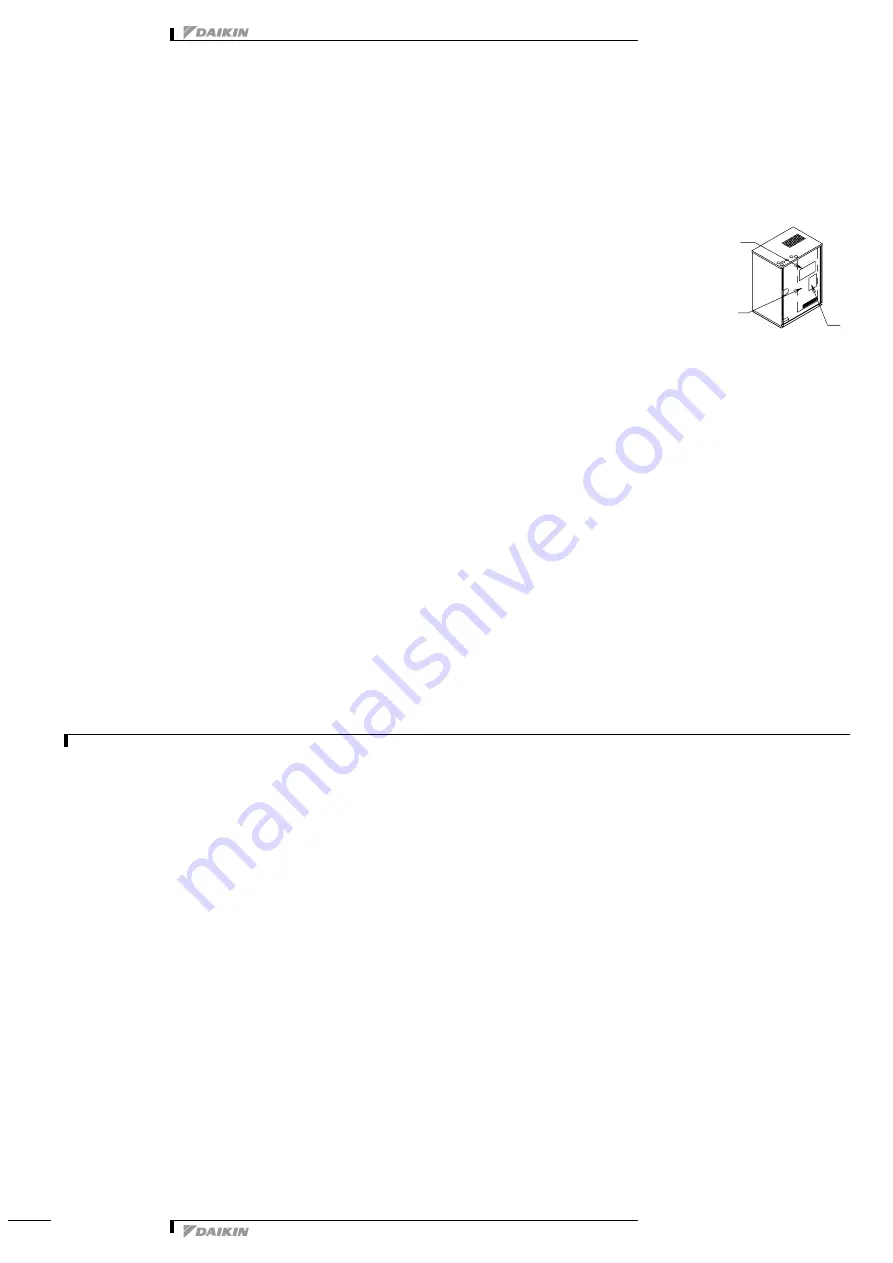
(For the service port location, refer to the “Caution” label attached on the front panel [right] of the outside unit.)

(Refer to figure)

[Service precautions] Label

EL. COMPO. BOX cover

[Caution] Label

Pressurize the liquid and gas pipes to 4.0MPa (40bar) (do not pressurize more than 4.0MPa (40bar)). If the pressure does 
not drop within 24 hours, the system passes the test. If the pressure drops, check where the nitrogen leaks from.

Vacuum drying:

 Use a vacuum pump which can evacuate to –100.7kPa (5Torr, –755mmHg).

1Evacuate the system from the liquid and gas pipes by using a vacuum pump for more than 2 hours and bring the system to –100.7kPa or less. 

After keeping the system under that condition for more than 1 hour, check if the vacuum gauge rises or not. If it rises, the system may either 
contain moisture inside or have leaks.

2Following should be executed if there is a possibility of moisture remaining inside the pipe (if piping work is carried out during the raining season 

or over a long period of time rainwater may enter the pipe during work).
After evacuating the system for 2 hours, pressurize the system to 0.05MPa (vacuum break) with nitrogen gas and evacuate the system again 
using the vacuum pump for 1 hour to –100.7kPa or less (vacuum drying). If the system cannot be evacuated to –100.7kPa within 2 hours, 
repeat the operation of vacuum break and vacuum drying.
Then, after leaving the system in vacuum for 1 hour, confirm that the vacuum gauge does not rise.

1 - 8 - 6

Pipe insulation

After finishing the leak test and vacuum drying, the piping must be insulated. Take into account the following points:

Make sure to insulate the connection piping both liquid-side and gas-side and refrigerant branch kits entirely.
Not insulating them may cause leaking. (The gas piping can reach temperatures of 120°C. Be sure the insulation used can withstand such 
temperatures.)

Reinforce the insulation on the refrigerant piping according to the installation environment. Condensation might form on the surface of the 
insulation.

If there is a possibility that condensation on the shutoff valve might drip down into the indoor unit through gaps in the insulation and piping because 
the outside unit is located higher than the indoor unit, etc., this must be prevented by caulking the connections, etc.

C

AUTION

Be sure to insulate connection piping, as touching them can cause burns.

1 - 8 - 7

Checking of device and installation conditions

Be sure to check the followings.

1

Make sure there is no faulty power wiring or loosing of a nut.
See “

10-8 Field wiring

”.

2

Make sure there is no faulty transmission wiring or loosing of a nut.
See “

10-8 Field wiring

”.

3

Make sure there is no faulty refrigerant piping.
See “

10-9 Refrigerant piping

”.

4

Make sure piping size is correct.
See “1

0-9-1 Selection of piping material

”.

5

Make sure insulation work is done.
See “

10-9-7 Pipe insulation

”.

6

Make sure insulation resistance of main power circuit is not deteriorated.
Using a megatester for 500V, check that the insulation resistance of 2M or more is attained by applying a voltage of 500V DC between power 
terminals and earth. Never use the megatester for the transmission wiring (between outdoor and indoor unit, outdoor and COOL/HEAT selector 
and etc.).

1

2

3

Summary of Contents for VRV-WII FXYCP30MY1

Page 1: ...technical data InstallationProcedure air conditioning systems EEDEN08 201 2b...

Page 2: ...n procedure 1 Installation of outdoor 2 Introduction 3 Selection of location 5 Inspecting and handling the unit 6 Unpacking and placing the unit 7 Water piping work 8 Handling of the plate type heat e...

Page 3: ...ing copper pipes or soldered parts may result in refrigerant leakage c near machinery emitting electromagnetic waves Electromagnetic waves may disturb the operation of the control system and result in...

Page 4: ...tible with R410A refer to the product catalogs Total capacity quantity of indoor units Outside unit Total capacity index of indoor units Total quantity of indoor units RWEYQ10MY1 125 325 16 units RWEY...

Page 5: ...0 x 2 1000 x 780 x 550 x 3 Mass kg 150 150 x 2 150 x 3 Connections Refrigerant liquid pipe inch 3 8 5 8 3 4 mm 9 5 28 6 19 1 Refrigerant gas pipe inch 7 8 1 1 8 1 3 8 mm 22 2 28 6 34 9 Refrigerant dis...

Page 6: ...tween the outside unit and the indoor unit may not exceed the allowable piping length 10 9 Refrigerant piping 5 Locations where the noise of the unit operating will not disturb nearby houses etc 6 Loc...

Page 7: ...caused by the corrosion of metal materials and clogging of the heat exchanger 5 The refrigerant R410A itself is nontoxic nonflammable and is safe If the refrigerant should leak however its concentrat...

Page 8: ...vailable M12 type foundation bolts nuts and washers The foundation bolts should be inserted 20 mm Fix 4 foundation bolts Support the unit with the foundation which is larger than the hatched area show...

Page 9: ...t any clogging by dust Do not connect the drain outlet to the water outlet Install a strainer an optional accessory in the inlet of water piping within a distance of 1 5 m from the outside unit If san...

Page 10: ...be caused during severe winter due to freezing in addition to thermal loss 6 When you stop operation during night or winter it is necessary to take measures to prevent water related circuits from natu...

Page 11: ...6 NOTES 1 The circle marks in the columns for corrosion or scale to develop 2 Corrosion has a tendency to occur when water temperature is high 40 C or higher and if metals with no protective coating...

Page 12: ...d nitric acid etc because they have strong corrosive features Make sure that a valve has been reserved for each before the inlet connection port and after the outlet connection port Connect the piping...

Page 13: ...e product in reversed phase may break the compressor and other parts Attach the power wire securely Introducing power with a missing N phase or with a mistaken N phase will break the equipment 1 7 1 O...

Page 14: ...gas pipes sewage pipes lightning rods or telephone ground wires Gas pipes can explode or catch fire if there is a gas leak Sewage pipes no grounding effect is possible if hard plastic piping is used...

Page 15: ...g should be secured as described in Field line connection transmission wiring and COOL HEAT selector 5 Secure the wiring with the accessory clamps so that it does not touch the piping 6 Make sure the...

Page 16: ...re no polarity Terminal board field supply Indoor unit Never connect the power wire BS unit A BS unit B Last BS unit Cool only unit In case of RWEYQ20 30MY1 Unit A Master unit Unit B Unit C TO IN D UN...

Page 17: ...eration circuit shall be set between terminals 1 and 2 Contact specification 220 VAC 3mA 0 5A PC board A1P Mount an insulation sleeve Connection of interlock circuit Do not forget to connect an interl...

Page 18: ...sheathed vinyl cords with 0 75 to 1 25 mm2 or cables 2 core wires 3 core wire are allowable for the COOL HEAT selector only All transmission wire is field supply If the following limits should be exc...

Page 19: ...leakage breaker Attach insulation sleeves Power supply terminal block Grounding terminal Retain the ground wires along with the power wires using the accessory clamp A Grounding wire When wiring do n...

Page 20: ...ng and ground jumper wiring Retain the power supply wiring pump operation output high voltage and ground wiring with the accessory clamp B to prevent them from touching with the stop valve for dischar...

Page 21: ...oned in the table below refer to the equipment design materials and service manual CAUTION A separate adapter sold separately as an accessory for external control of an outside unit becomes necessary...

Page 22: ...the system while the pump is not working 3Use a vacuum pump which can evacuate to 100 7 kPa 5Torr 755mmHg 1 8 1 Selection of piping material 1 Foreign materials inside pipes including oils for fabric...

Page 23: ...on nameplate Horizontal line Ground Straight part of 500mm or more Local pipe 120mm length or more Precautions when selecting branch piping If the equivalent length of piping between the outside units...

Page 24: ...autions when connecting pipes See the following table for flare part machining dimensions When connecting the flare nuts apply refrigerant oil to the inside and outside of the flares and screw them in...

Page 25: ...f the hatched area and use it as a cover for the drilled Hatched area Accessory pipe for discharge gas Accessory pipe for suction gas Guideline for pipe machining Accessory pipe for suction gas 2 Braz...

Page 26: ...ing causing any damage to the outside unit 3 If the piping length between the outside unit connecting pipe kit or between the outside units exceeds 2 m create a rise of 200 mm or more in the gas line...

Page 27: ...to 100 7kPa within 2 hours repeat the operation of vacuum break and vacuum drying Then after leaving the system in vacuum for 1 hour confirm that the vacuum gauge does not rise 1 8 6 Pipe insulation...

Page 28: ...front cover NOTE Refer to the example of connection for the amount to be added Additional refrigerant charge procedure 1 normally Charge the refrigerant to the liquid pipe in its liquid state Since R4...

Page 29: ...arging additional refrigerant Pressure reducing valve Nitrogen Refrigerant tank With a siphon Measuring instrument Vacuum pump Val ve A Val ve B Charge hose Outside unit Gas side Liquid side Discharge...

Page 30: ...then open the valve by turning 180 Start the additional refrigerant charge operation See Service precautions Label for detail If it is difficult to charge the refrigerant additionally decrease the wat...

Page 31: ...to the shutoff valve Doing so may break the valve body as the valve is not a backseat type Always use the hexagon wrench 3 Make sure to tighten the cap securely Closing shutoff valve 1 Remove the cap...

Page 32: ...turns as the initial tightening 7 Do not forget to open the stop valve before starting operation Remove the cap and turn the valve counter clockwise with the hexagon wrenches until it stops Discharge...

Page 33: ...not be operated at a temperature outside the operation range 6 Check the LED on the PC board A1P in the outside unit to see if the data transmission is performed normally The master unit is the outsid...

Page 34: ...toff valve of an outside unit is left closed Open the shutoff valve U1 The phases of the power to the outside units are reversed Exchange two of the three phases L1 L2 L3 to make a positive phase conn...

Page 35: ...ted therein Specifications are subject to change without prior notice Daikin Europe N V explicitly rejects any liability for any direct or indirect damage In the broadest sense arising from or related...

Reviews: