


Introduction
Si37-701
viii
1.1.3 Inspection after Repair
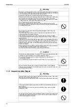
Be sure to use the specified cable to connect between the indoor and outdoor
units. Make the connections securely and route the cable properly so that there
is no force pulling the cable at the connection terminals.
Improper connections can cause excessive heat generation or fire.
When connecting the cable between the indoor and outdoor units, make sure
that the terminal cover does not lift off or dismount because of the cable.
If the cover is not mounted properly, the terminal connection section can cause
an electrical shock, excessive heat generation or fire.
Do not damage or modify the power cable.
Damaged or modified power cable can cause an electrical shock or fire.
Placing heavy items on the power cable, and heating or pulling the power cable
can damage the cable.
Do not mix air or gas other than the specified refrigerant (R-410A) in the
refrigerant system.
If air enters the refrigerating system, an excessively high pressure results,
causing equipment damage and injury.
If the refrigerant gas leaks, be sure to locate the leak and repair it before
charging the refrigerant. After charging refrigerant, make sure that there is no
refrigerant leak.
If the leak cannot be located and the repair work must be stopped, be sure to
perform pump-down and close the service valve, to prevent the refrigerant gas
from leaking into the room. The refrigerant gas itself is harmless, but it can
generate toxic gases when it contacts flames, such as fan and other heaters,
stoves and ranges.
When replacing the coin battery in the remote controller, be sure to disposed
of the old battery to prevent children from swallowing it.
If a child swallows the coin battery, see a doctor immediately.
Warning
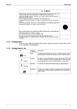
Caution
Installation of a leakage breaker is necessary in some cases depending on the
conditions of the installation site, to prevent electrical shocks.
Do not install the equipment in a place where there is a possibility of
combustible gas leaks.
If a combustible gas leaks and remains around the unit, it can cause a fire.
Be sure to install the packing and seal on the installation frame properly.
If the packing and seal are not installed properly, water can enter the room and
wet the furniture and floor.
For integral units
only
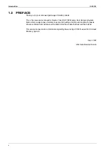
Warning
Check to make sure that the power cable plug is not dirty or loose, then insert
the plug into a power outlet all the way.
If the plug has dust or loose connection, it can cause an electrical shock or fire.
If the power cable and lead wires have scratches or deteriorated, be sure to
replace them.
Damaged cable and wires can cause an electrical shock, excessive heat
generation or fire.
Do not use a joined power cable or extension cable, or share the same power
outlet with other electrical appliances, since it can cause an electrical shock,
excessive heat generation or fire.
Summary of Contents for VRV III REYQ10PY1
Page 1: ...REYQ8 48PY1 R 410A Heat Recovery 50Hz Si37 701 ...
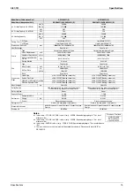
Page 59: ...Specifications Si37 701 48 Specifications ...
Page 105: ...Refrigerant Flow for Each Operation Mode Si37 701 94 Refrigerant Circuit ...
Page 230: ...Si37 701 Troubleshooting by Remote Controller Troubleshooting 219 ...
Page 374: ...Si37 701 Piping Diagrams Appendix 363 REYQ14P 16PY1 3D058153A S2NPL S1NPH ...
Page 375: ...Piping Diagrams Si37 701 364 Appendix REMQ8PY1 3D057743 ...
Page 376: ...Si37 701 Piping Diagrams Appendix 365 REMQ10PY1 12PY1 3D057742 ...
Page 377: ...Piping Diagrams Si37 701 366 Appendix REMQ14PY1 16PY1 3D057741 ...
Page 382: ...Si37 701 Piping Diagrams Appendix 371 1 3 BS Unit 4D057985A ...
Page 384: ...Si37 701 Wiring Diagrams for Reference Appendix 373 REYQ14 16PY1 3D056774C ...
Page 385: ...Wiring Diagrams for Reference Si37 701 374 Appendix REMQ8PY1 3D055307E ...
Page 386: ...Si37 701 Wiring Diagrams for Reference Appendix 375 REMQ10 12PY1 3D055308E ...
Page 387: ...Wiring Diagrams for Reference Si37 701 376 Appendix REMQ14P 16PY1 3D055309E ...
Page 392: ...Si37 701 Wiring Diagrams for Reference Appendix 381 FXCQ40M 50M 80M 125MVE 3D039557A ...
Page 394: ...Si37 701 Wiring Diagrams for Reference Appendix 383 FXZQ20M 25M 32M 40M 50M8V1B 3D038359 ...
Page 395: ...Wiring Diagrams for Reference Si37 701 384 Appendix FXKQ25MA 32MA 40MA 63MAVE 3D039564C ...
Page 399: ...Wiring Diagrams for Reference Si37 701 388 Appendix FXDYQ180M 200M 250MV1 ...
Page 402: ...Si37 701 Wiring Diagrams for Reference Appendix 391 FXMQ200MA 250MAVE 3D039621B ...
Page 403: ...Wiring Diagrams for Reference Si37 701 392 Appendix FXHQ32MA 63MA 100MAVE 3D039801D ...
Page 406: ...Si37 701 Wiring Diagrams for Reference Appendix 395 2 4 BS Unit 3D055928C ...
Page 423: ...Piping Installation Point Si37 701 412 Appendix ...
Page 427: ...Example of Connection R 410A Type Si37 701 416 Appendix ...
Page 433: ...Method of Checking the Inverter s Power Transistors and Diode Modules Si37 701 422 Appendix ...
Page 447: ...Si37 701 iv Index ...


