


Si37-701
Troubleshooting (OP: Unified ON/OFF Controller)
Troubleshooting
357
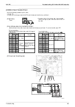
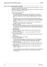
[Check 12] Check for shortage of refrigerant.
In case of VRV Systems, the only way to judge as the shortage of refrigerant is with operating
conditions due to the relationship to pressure control and electronic expansion valve control.
As information for making a judgment, refer to information provided below.
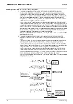
Diagnosis of shortage of refrigerant
1. The superheated degree of suction gas rises. Consequently, the compressor discharge gas
temperature becomes higher.
2. The superheated degree of suction gas rises. Consequently, the electronic expansion valve
turns open.
3. Low pressure drops to cause the unit not to demonstrate cooling capacity (heating capacity).
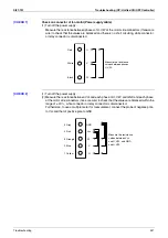
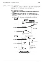
Cooling
High pressure
Low pressure
Frequency
The opening degree of the indoor unit
motorized valve becomes larger.
Either of the motorized valves
becomes fully open.
Frequency comes to the minimum level.
Fan control is activated for HP
protection under cooling control
at low outdoor temperature,
i.e., the fan is hunting at HP.
HP drops with decrease
in compressor capacity.
If frequency comes to the
minimum level, LP
cannot be maintained.
LP rises as the opening
degree of the indoor unit
motorized valve becomes
larger. Frequency slightly
increases under the
capacity control.
To maintain LP,
frequency drops
due to the
capacity control.
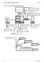
Heating
High pressure
Low pressure
Frequency
The opening degree of the outdoor unit motorized valve becomes larger.
The outdoor unit motorized valve fully opens and frequency increases.
Discharge pipe or LP drooping control
(HP is maintained
at a constant level.)
Frequency comes to
the minimum level.
To maintain LP, frequency
drops due to the capacity
control.
Frequency drops
due to the drooping
control.
(Degree of refrigerant shortage)
Higher degree of shortage
Proper quantity
(LP is maintained
at a constant level.)
Summary of Contents for VRV III REYQ10PY1
Page 1: ...REYQ8 48PY1 R 410A Heat Recovery 50Hz Si37 701 ...
Page 59: ...Specifications Si37 701 48 Specifications ...
Page 105: ...Refrigerant Flow for Each Operation Mode Si37 701 94 Refrigerant Circuit ...
Page 230: ...Si37 701 Troubleshooting by Remote Controller Troubleshooting 219 ...
Page 374: ...Si37 701 Piping Diagrams Appendix 363 REYQ14P 16PY1 3D058153A S2NPL S1NPH ...
Page 375: ...Piping Diagrams Si37 701 364 Appendix REMQ8PY1 3D057743 ...
Page 376: ...Si37 701 Piping Diagrams Appendix 365 REMQ10PY1 12PY1 3D057742 ...
Page 377: ...Piping Diagrams Si37 701 366 Appendix REMQ14PY1 16PY1 3D057741 ...
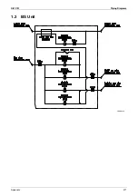
Page 382: ...Si37 701 Piping Diagrams Appendix 371 1 3 BS Unit 4D057985A ...
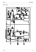
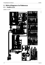
Page 384: ...Si37 701 Wiring Diagrams for Reference Appendix 373 REYQ14 16PY1 3D056774C ...
Page 385: ...Wiring Diagrams for Reference Si37 701 374 Appendix REMQ8PY1 3D055307E ...
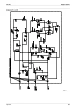
Page 386: ...Si37 701 Wiring Diagrams for Reference Appendix 375 REMQ10 12PY1 3D055308E ...
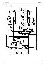
Page 387: ...Wiring Diagrams for Reference Si37 701 376 Appendix REMQ14P 16PY1 3D055309E ...
Page 392: ...Si37 701 Wiring Diagrams for Reference Appendix 381 FXCQ40M 50M 80M 125MVE 3D039557A ...
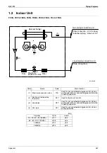
Page 394: ...Si37 701 Wiring Diagrams for Reference Appendix 383 FXZQ20M 25M 32M 40M 50M8V1B 3D038359 ...
Page 395: ...Wiring Diagrams for Reference Si37 701 384 Appendix FXKQ25MA 32MA 40MA 63MAVE 3D039564C ...
Page 399: ...Wiring Diagrams for Reference Si37 701 388 Appendix FXDYQ180M 200M 250MV1 ...
Page 402: ...Si37 701 Wiring Diagrams for Reference Appendix 391 FXMQ200MA 250MAVE 3D039621B ...
Page 403: ...Wiring Diagrams for Reference Si37 701 392 Appendix FXHQ32MA 63MA 100MAVE 3D039801D ...
Page 406: ...Si37 701 Wiring Diagrams for Reference Appendix 395 2 4 BS Unit 3D055928C ...
Page 423: ...Piping Installation Point Si37 701 412 Appendix ...
Page 427: ...Example of Connection R 410A Type Si37 701 416 Appendix ...
Page 433: ...Method of Checking the Inverter s Power Transistors and Diode Modules Si37 701 422 Appendix ...
Page 447: ...Si37 701 iv Index ...


